Nissan Sentra Service Manual: P0712 Transmission fluid temperature sensor A
DTC Logic
DTC DETECTION LOGIC
| DTC | CONSULT screen terms (Trouble diagnosis content) | DTC detection condition | Possible causes |
| P0712 | FLUID TEMP SENSOR A (Transmission Fluid Temperature Sensor A Circuit Low) | The CVT fluid temperature identified by the
TCM is 180В°C (356В°F) or more continuously
for 5 seconds or more under the following diagnosis
conditions: Diagnosis conditions
|
|
DTC CONFIRMATION PROCEDURE
1.PREPARATION BEFORE WORK
If another “DTC CONFIRMATION PROCEDURE” occurs just before, turn ignition switch OFF and wait for at least 10 seconds, then perform the next test.
>> GO TO 2.
2.PERFORM DTC CONFIRMATION PROCEDURE
- Start the engine and wait for 10 seconds or more.
- Check the first trip DTC.
Is “P0712” detected? YES >> Go to TM-174, "Diagnosis Procedure".
NO >> INSPECTION END
Diagnosis Procedure
1.CHECK CIRCUIT BETWEEN TCM AND CVT UNIT
- Turn ignition switch OFF.
- Disconnect TCM connector and CVT unit connector.
- Check continuity between TCM harness connector terminal and ground.
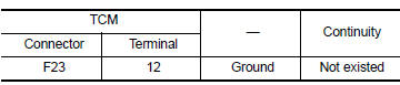
Is the inspection result normal? YES >> GO TO 2.
NO >> Repair or replace malfunctioning part.
2.CHECK CVT FLUID TEMPERATURE SENSOR
Check CVT fluid temperature sensor. Refer to TM-174, "Component Inspection".
Is the inspection result normal? YES >> Check intermittent incident. Refer to GI-39, "Intermittent Incident".
NO >> Repair or replace malfunctioning parts.
Component Inspection
1.CHECK CVT FLUID TEMPERATURE SENSOR
Check resistance between CVT unit connector terminals.
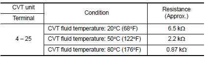
Is the inspection result normal? YES >> INSPECTION END
NO >> There is a malfunction of CVT fluid temperature sensor. Replace transaxle assembly. Refer to TM-283, "Removal and Installation".
 P0711 Transmission fluid temperature sensor A
DTC Logic
DTC DETECTION LOGIC
DTC
CONSULT screen terms
(Trouble diagnosis content)
DTC detection condition
Possible causes
P0711
FLUID TEMP SENSOR A
(Transmission F ...
 P0713 Transmission fluid temperature sensor A
DTC Logic
DTC DETECTION LOGIC
DTC
CONSULT screen terms
(Trouble diagnosis content)
DTC detection condition
Possible causes
P0713
FLUID TEMP SENSOR A
(Transmission ...
Other materials:
Battery terminal with fusible link
Exploded view
Battery terminal with fusible link
Harness connector
Removal and installation
Removal
Loosen the battery terminal nuts and disconnect both battery negative and
positive terminals. Refer to
pg-50, "exploded view".
Caution:
To prevent damage to the parts, di ...
Bcm branch line circuit
Diagnosis procedure
1.Check connector
Turn the ignition switch off.
Disconnect the battery cable from the negative terminal.
Check the terminals and connectors of the BCM for damage, bend and loose
connection (unit side and
connector side).
Is the inspection result normal?
YES > ...
P0720 Output speed sensor
DTC Logic
DTC DETECTION LOGIC
DTC
CONSULT screen terms
(Trouble diagnosis content)
DTC detection condition
Possible causes
P0720
OUTPUT SPEED SENSOR
(Output Speed Sensor Circuit)
The output speed sensor value is less than
150 rpm continuously for 5 seconds ...
