Nissan Sentra Service Manual: P0181 FTT Sensor
DTC Logic
DTC DETECTION LOGIC
| DTC No. | CONSULT screen terms (Trouble diagnosis content) | DTC detecting condition | Possible cause | |
| P0181 | FTT SENSOR (Fuel temperature sensor ″A″ circuit range/performance) | A) | Rationally incorrect voltage from the sensor is sent to ECM, compared with the voltage signals from ECT sensor and intake air temperature sensor. |
|
| B) | The comparison result of signals transmitted to ECM from each temperature sensor (IAT sensor, ECT sensor, EOT sensor, and FTT sensor) shows that the voltage signal of the FTT sensor is higher/lower than that of other temperature sensors when the engine is started with its cold state. |
|
||
DTC CONFIRMATION PROCEDURE
1.INSPECTION START
Is it necessary to erase permanent DTC? YES >> GO TO 7.
NO >> GO TO 2.
2.PRECONDITIONING
If DTC CONFIRMATION PROCEDURE has been previously conducted, always perform the following procedure before conducting the next test.
- Turn ignition switch OFF and wait at least 10 seconds.
- Turn ignition switch ON.
- Turn ignition switch OFF and wait at least 10 seconds.
>> GO TO 3.
3.PERFORM DTC CONFIRMATION PROCEDURE FOR MALFUNCTION A-1
- Turn ignition switch ON and wait at least 10 seconds.
- Check 1st trip DTC.
Is 1st trip DTC detected? YES >> Proceed to EC-256, "Diagnosis Procedure".
NO >> GO TO 4.
4.CHECK ENGINE COOLANT TEMPERATURE
 With CONSULT
- Select “COOLANT TEMP/S” in “DATA MONITOR” of “ENGINE” using CONSULT.
- Check “COOLANT TEMP/S” value.
 With GST
Follow the procedure “With CONSULT” above.
“COOLANT TEMP/S” less than 60°C (140°F)? YES >> INSPECTION END
NO >> GO TO 5.
5.PERFORM DTC CONFIRMATION PROCEDURE FOR MALFUNCTION A-2
 With CONSULT
- Cool engine down until “COOLANT TEMP/S” is less than 60°C (140°F).
- Wait at least 10 seconds.
- Check 1st trip DTC.
 With GST
Follow the procedure “With CONSULT” above.
Is 1st trip DTC detected? YES >> Proceed to EC-256, "Diagnosis Procedure".
NO >> GO TO 6.
6.PERFORM COMPONENT FUNCTION CHECK (FOR MALFUNCTION B)
Perform component function check. Refer to EC-255, "Component Function Check".
NOTE:
Use the component function check to check the overall function of the FTT sensor circuit. During this check, a 1st trip DTC might not be confirmed.
Is the inspection result normal? YES >> INSPECTION END
NO >> Proceed to EC-256, "Diagnosis Procedure".
7.PRECONDITIONING
If DTC CONFIRMATION PROCEDURE has been previously conducted, always perform the following procedure before conducting the next test
- Turn ignition switch OFF and wait at least 10 seconds.
- Turn ignition switch ON.
- Turn ignition switch OFF and wait at least 10 seconds.
TESTING CONDITION:
- Before performing the following procedure, do not add fuel.
- Before performing the following procedure, check that fuel level is between 1/4 and 4/4.
- Before performing the following procedure, confirm that battery voltage is 11 V or more at idle.
>> GO TO 8.
8.PERFORM DTC CONFIRMATION PROCEDURE B
- Move the vehicle to a cool place.
NOTE:
Cool the vehicle in an environment of ambient air temperature between −10В°C (14В°F) and 35В°C (95В°F).
- Turn ignition switch OFF and leave the vehicle for 12 hours.
CAUTION:
Never turn ignition switch ON during this procedure.
NOTE:
The vehicle must be cooled with the food open.
- Start engine and let it idle for 5 minutes or more.
CAUTION:
Never turn ignition switch OFF during idling.
- Check 1st trip DTC.
Is 1st trip DTC detected? YES >> Proceed to EC-256, "Diagnosis Procedure".
NO >> INSPECTION END
Component Function Check
1.CHECK FUEL TANK TEMPERATURE (FTT) SENSOR
- Turn ignition switch OFF.
- Disconnect fuel level sensor unit and fuel pump harness connector
- Remove fuel level sensor unit. Refer to FL-6, "Removal and Installation".
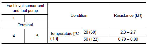
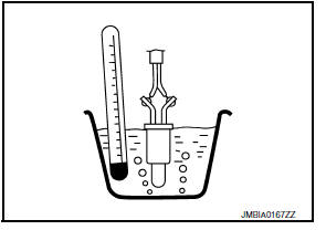
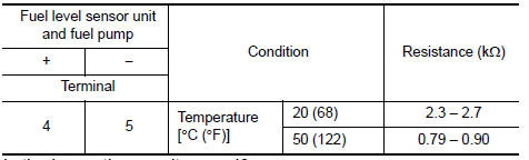
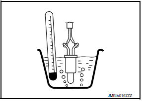
- Check resistance between fuel level sensor unit and fuel pump terminals by heating with hot water as shown in the figure.
Is the inspection result normal? YES >> Check intermittent incident. Refer to GI-39, "Intermittent Incident".
NO >> Proceed to EC-256, "Diagnosis Procedure".
Diagnosis Procedure
1.INSPECTION START
Confirm the detected malfunction (A or B). Refer to EC-254, "DTC Logic".
Which malfunction is detected? A >>GO TO 2.
B >>GO TO 6.
2.CHECK DTC WITH COMBINATION METER
Check DTC with combination meter. Refer to MWI-17, "CONSULT Function (METER/M&A)".
Is the inspection result normal? YES >> GO TO 3.
NO >> Proceed to MWI-58, "Diagnosis Procedure".
3.CHECK FUEL TANK TEMPERATURE (FTT) SENSOR POWER
- Turn ignition switch OFF.
- Disconnect fuel level sensor unit and fuel pump harness connector.
- Turn ignition switch ON.
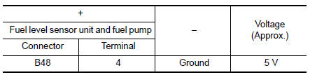
- Check the voltage between fuel level sensor unit and fuel pump harness connector and ground.
Is the inspection result normal? YES >> GO TO 5.
NO >> GO TO 4.
4.CHECK FUEL TANK TEMPERATURE (FTT) SENSOR POWER SUPPLY CIRCUIT
- Turn ignition switch OFF.
- Disconnect ECM harness connector.
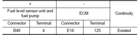
- Check the continuity between fuel level sensor unit and fuel pump harness connector and ECM harness connector.
- Also check harness for short to ground and to power.
Is the inspection result normal? YES >> Perform the trouble diagnosis for power supply circuit.
NO >> Repair or replace error-detected parts.
5.CHECK FTT SENSOR GROUND CIRCUIT
- Turn ignition switch OFF.
- Disconnect ECM harness connector.
- Check the continuity between fuel level sensor unit and fuel pump harness connector and ECM harness connector.
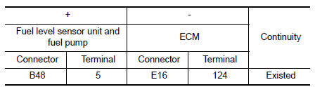
- Also check harness for short to power.
Is the inspection result normal? YES >> GO TO 6.
NO >> Repair or replace error-detected parts.
6.CHECK FUEL TANK TEMPERATURE (FTT) SENSOR
Check the FTT sensor. Refer to EC-257, "Component Inspection".
Is the inspection result normal? YES >> Check intermittent incident. Refer to GI-39, "Intermittent Incident".
NO >> Replace fuel level sensor unit and fuel pump. Refer to FL-6, "Removal and Installation".
Component Inspection
1.CHECK FUEL TANK TEMPERATURE (FTT) SENSOR
- Turn ignition switch OFF.
- Disconnect fuel level sensor unit and fuel pump harness connector
- Remove fuel level sensor unit. Refer to FL-6, "Removal and Installation".
- Check resistance between fuel level sensor unit and fuel pump terminals by heating with hot water as shown in the figure.
Is the inspection result normal? YES >> INSPECTION END
NO >> Replace fuel level sensor unit and fuel pump. Refer to FL-6, "Removal and Installation".
 P0172 Fuel injection system function
DTC Logic
DTC DETECTION LOGIC
With the Air/Fuel Mixture Ratio Self-Learning Control, the actual mixture
ratio can be brought closely to the
theoretical mixture ratio based on the mixture ratio fe ...
 P0182, P0183 FTT Sensor
DTC Logic
DTC DETECTION LOGIC
DTC No.
CONSULT screen terms
(Trouble diagnosis content)
DTC detecting condition
Possible cause
P0182
FTT SEN/CIRCUIT
(Fuel temperatur ...
Other materials:
Basic inspection
DIAGNOSIS AND REPAIR WORK FLOW
Work Flow
NOTE:
“DTC” includes DTC at the 1st trip.
1.OBTAIN INFORMATION ABOUT SYMPTOM
Refer to TM-140, "Diagnostic Work Sheet" and interview the customer to obtain
the malfunction information
(conditions and environment when the malfunctio ...
Sunshade
Exploded View
Sunshade
Moonroof unit assembly
Sunshade stopper (LH/RH)
Front
Removal and Installation
REMOVAL
Remove the headlining. Refer to INT-40, "Removal and Installation".
Remove the sunshade stoppers (1) (LH/RH) from the moonroof
unit assembly side rails (2) ...
Service data and specifications (SDS)
Road Wheel
Tire Air Pressure
M/T - CVT MODELS
CVT MODELS
...
