Nissan Sentra Service Manual: Overdrive control switch
Component Function Check
1.CHECK SPORT INDICATOR LAMP FUNCTION
Check OD OFF indicator lamp turns ON for approx. 2 seconds when ignition switch turns ON.
Is the inspection result normal? YES >> GO TO 2.
NO >> Go to TM-239, "Diagnosis Procedure".
2.CHECK SPORT MODE SWITCH FUNCTION
- Shift the selector lever to “D” position.
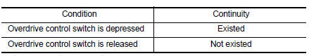
- Check that OD OFF indicator lamp turns ON/OFF when overdrive control switch is operated.
Is the inspection result normal? YES >> INSPECTION END
NO >> Go to TM-236, "Diagnosis Procedure".
Diagnosis Procedure
1.CHECK OVERDRIVE CONTROL SWITCH CIRCUIT
- Turn ignition switch OFF
- Disconnect CVT shift selector connector.
- Turn ignition switch ON.
- Check voltage between CVT shift selector harness connector terminals.
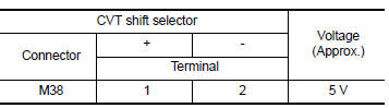 Is the inspection
result normal?
YES >> GO TO 2.
NO >> GO TO 4.
2.CHECK CVT SHIFT SELECTOR ASSEMBLY
Check continuity between CVT shift selector connector terminals.
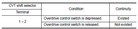 Is the inspection
result normal?
YES >> Check intermittent incident. Refer to GI-39, "Intermittent Incident".
NO >> GO TO 3.
3.CHECK OVERDRIVE CONTROL SWITCH
Check overdrive control switch. Refer to TM-237, "Component Inspection (Overdrive Control Switch)".
Is the inspection result normal? YES >> Replace CVT shift selector assembly. Refer to TM-253, "Removal and Installation".
NO >> Repair or replace malfunctioning parts.
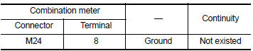
4.CHECK GROUND CIRCUIT
Check continuity between CVT shift selector harness connector terminal and ground.
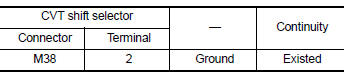 Is the inspection
result normal?
YES >> GO TO 5.
NO >> Repair or replace malfunctioning parts.
5.CHECK CIRCUIT BETWEEN COMBINATION METER AND CVT SHIFT SELECTOR (PART 1)
- Turn ignition switch OFF
- Disconnect combination meter connector.
- Check continuity between combination meter harness connector terminal and CVT shift selector harness connector terminal.
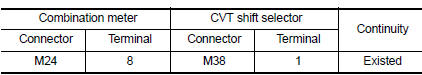 Is the inspection
result normal?
YES >> GO TO 6.
NO >> Repair or replace malfunctioning parts.
6.CHECK CIRCUIT BETWEEN COMBINATION METER AND CVT SHIFT SELECTOR (PART 2)
Check continuity between combination meter harness connector terminal and ground.
 Is the inspection
result normal?
YES >> GO TO 7.
NO >> Repair or replace malfunctioning parts.
7.CHECK COMBINATION METER INPUT SIGNAL
- Connect all of disconnected connectors.
- Turn ignition switch ON.
- Select “Data Monitor” in “METER/M&A”.
- Select “O/D OFF SW”.
- Check that “O/D OFF SW” turns ON/OFF when overdrive control switch is operated. Refer to MWI-20, "Reference Value".
Is the inspection result normal? YES >> Check intermittent incident. Refer to GI-39, "Intermittent Incident".
NO >> Replace combination meter. Refer to MWI-77, "Removal and Installation".
Component Inspection (Overdrive Control Switch)
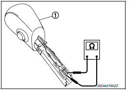
1.Check overdrive control switch
Check continuity between wires of selector lever knob 1.
 Is the inspection
result normal?
YES >> INSPECTION END
NO >> Replace selector lever knob. Refer to TM-253, "Removal and Installation".
 Main power supply and ground circuit
Diagnosis Procedure
1.CHECK TCM POWER CIRCUIT (PART 1)
Turn ignition switch OFF.
Disconnect TCM connector.
Check voltage between TCM harness connector terminals and ground.
Is the insp ...
 Od off indicator lamp
Component Function Check
1.CHECK OD OFF INDICATOR LAMP FUNCTION
Check OD OFF indicator lamp turns ON for approx. 2 seconds when ignition
switch turns ON.
Is the inspection result normal?
YES ...
Other materials:
Cooling fan
Component
Fan shroud and motor assembly
WARNING:
Do not remove the radiator cap when the engine is hot. Serious burns
could occur from high-pressure
engine coolant escaping from the radiator. Wrap a thick cloth around the cap.
Slowly push down and
turn it a quarter turn to allow b ...
Warning lights
Anti-lock
Braking
System (ABS) warning light
When the ignition switch is placed in the ON
position, the Anti-lock Braking System (ABS)
warning light illuminates and then turns off. This
indicates the ABS is operational.
If the ABS warning light illuminates while the
engine is running or ...
Component parts
Component Parts Location
Driver air bag module
Front passenger air bag off indicator
Front passenger air bag module
Front LH side air bag module
(RH similar)
LH side curtain air bag module
(view with headliner removed)
(RH similar)
Front LH seatbelt pre-tensioner
(view wit ...
