Nissan Sentra Service Manual: Moonroof switch
Description
Transmits switch operation signal to moonroof motor assembly.
Diagnosis Procedure
Regarding Wiring Diagram information, refer to RF-13, "Wiring Diagram".
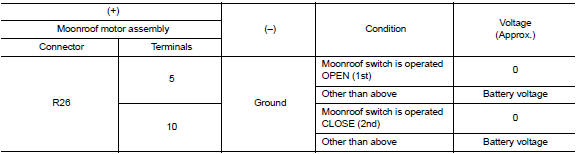
1.Check moonroof switch input signal
- Turn ignition switch on.
- Check voltage between moonroof motor assembly harness connector R26 and ground.
Is the inspection result normal? Yes >> inspection end.
No >> go to 2.
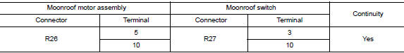
2.Check moonroof switch circuit
- Turn ignition switch OFF.
- Disconnect moonroof motor assembly connector and moonroof switch connector.
- Check continuity between moonroof motor assembly harness connector R26 and moonroof switch harness connector R27.
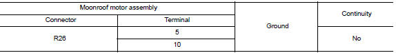
- Check continuity between moonroof motor assembly harness connector R26 and ground.
Is the inspection result normal? YES >> GO TO 3.
NO >> Repair or replace the harness or connectors.
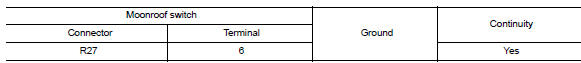
3.Check moonroof switch ground circuit
Check continuity between moonroof switch harness connector r27 and ground.
Is the inspection result normal? YES >> GO TO 4.
NO >> Repair or replace the harness or connectors.
4.Check moonroof switch
Check moonroof switch.
Refer to rf-25, "component inspection".
Is the inspection result normal? Yes >> go to 5.
No >> replace moonroof switch. Refer to rf-50, "removal and installation".
5.Check intermittent incident
Refer to gi-39, "intermittent incident".
>> Inspection end.
Component inspection
Moonroof switch
1. Check moonroof switch
- Turn ignition switch off.
- Disconnect moonroof switch.
- Check continuity between moonroof switch terminals.
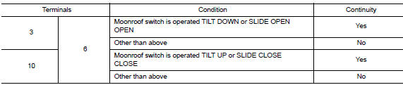
Is the inspection result normal? Yes >> moonroof switch is ok.
No >> replace moonroof switch. Refer to rf-50, "removal and installation".
 Power supply and ground circuit
Body control system
Body control system : diagnosis procedure
Regarding wiring diagram information, refer to bcs-51, "wiring diagram".
1.Check fuses and fusible link
Check that the follo ...
 Door switch
Component Function Check
1.Check function
Select DOOR LOCK of BCM using CONSULT
Select door sw-dr, door sw-as in data monitor mode
Check that the function operates normally according to the f ...
Other materials:
Precaution for Supplemental Restraint System (SRS) "AIR BAG" and "SEAT BELT
PRE-TENSIONER"
The Supplemental Restraint System such as “AIR BAG” and “SEAT BELT
PRE-TENSIONER”, used along
with a front seat belt, helps to reduce the risk or severity of injury to the
driver and front passenger for certain
types of collision. Information necessary to service the system ...
Removal and installation
Combination meter
Exploded view
Combination meter
Front cover
Removal and installation
Removal
Remove cluster lid a. Refer to ip-19, "removal and installation".
Remove the screws from the combination meter.
Remove the combination meter.
Disconnect the comb ...
Tire Pressure Monitoring System (TPMS)
Each tire, including the spare (if provided),
should be checked monthly when cold and inflated
to the inflation pressure recommended by
the vehicle manufacturer on the vehicle placard
or tire inflation pressure label. (If your vehicle has
tires of a different size than the size indicated on
th ...
