
Nissan Sentra Service Manual: Heating and cooling unit assembly
Exploded view
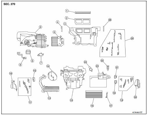
With air conditioning
- Defroster seal
- Center ventilator seal
- Upper distribution module
- Side ventilator seal (LH)
- Blower motor
- Blower unit
- Intake door motor
- Power transistor
- Power transistor wiring harness
- Front floor duct (lh)
- Vent and defroster linkage
- Mode door motor
- Heater core
- Heater core pipes grommet
- Heating and cooling unit
- In-cabin microfilter
- In-cabin microfilter cover
- Air mix door motor (lh) (automatic a/c only)
- Vent and defroster linkage
- Front floor duct (rh)
- Air mix door motor (RH)
- Expansion valve
- Evaporator
- Aspirator (automatic a/c only)
- Vent and defroster linkage
- Side ventilator seal (rh)
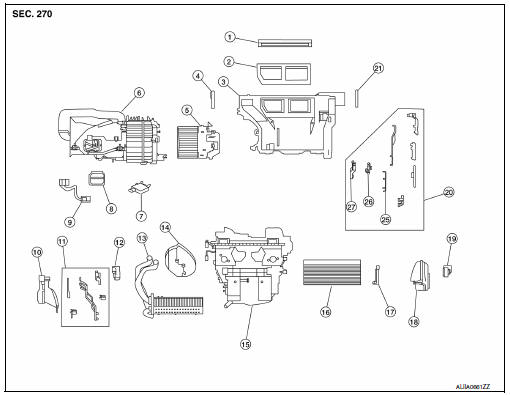
Without air conditioning
- Defroster seal
- Center ventilator seal
- Upper distribution module
- Side ventilator seal (lh)
- Blower motor
- Blower unit
- Intake door motor
- Power transistor
- Power transistor wiring harness
- Front floor duct (LH)
- Vent and defroster linkage
- Mode door motor
- Heater core
- Heater core pipes grommet
- Heating and cooling unit
- In-cabin microfilter
- In-cabin microfilter cover
- Front floor duct (RH)
- Air mix door motor
- Vent and defroster linkage
- Side ventilator seal (RH)
Heating and cooling unit assembly
Heating and cooling unit assembly : removal and installation
NOTE:
When removing components such as hoses, lines/tubes, etc., cap or plug openings to prevent fluid from spilling.
REMOVAL
- Discharge the refrigerant. Refer to HA-23, "Recycle Refrigerant".
- Drain the cooling system. Refer to CO-12, "Changing Engine Coolant".
- Remove the instrument panel assembly. Refer to IP-14, "Removal and Installation".
- Remove the steering column. Refer to ST-12, "Removal and Installation".
- Remove the center console. Refer to IP-17, "Removal and Installation".
- Remove the wiper drive assembly. Refer to WW-62, "Removal and Installation".
- Remove the steering member bolt (A).
(1): Windshield glass
NOTE:
The steering member bolt (A) can be found near the drivers side cowl area in the engine compartment.
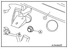
- Remove the push nut (A) from the expansion valve insulator (1) and reposition.
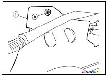
- Remove the bolt (A) that retains the low-pressure flexible hose and high-pressure pipe to the expansion valve.
CAUTION:
Cap or wrap the joint of the pipe with suitable material such as vinyl tape to avoid the entry of air.
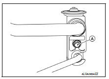
- Disconnect the low-pressure pipe and high-pressure pipe from the expansion valve.
- Disconnect the heater hoses from the heater core pipes.
- Remove the remaining steering member bolts.
- Disconnect the harness connectors from the heating and cooling unit assembly and steering member.
- Remove the heating and cooling unit assembly and steering member as an assembly from the vehicle.
- Separate the heating and cooling unit assembly from the steering member.
INSTALLATION
Installation is in the reverse order of removal.
CAUTION:
- Do not reuse O-rings.
- Apply A/C oil to new O-rings for installation.
- After charging refrigerant, check for leaks. Refer to HA-21, "Leak Test".
Heater core
Heater core : removal and installation
REMOVAL
The heater core is not serviced separately and must be replaced with the heating and cooling unit assembly.
Refer to HA-43, "HEATING AND COOLING UNIT ASSEMBLY : Removal and Installation".
Evaporator
Evaporator : removal and installation
REMOVAL
The evaporator is not serviced separately and must be replaced with the heating and cooling unit assembly.
Refer to HA-45, "EVAPORATOR : Removal and Installation".
Expansion valve
Expansion valve : removal and installation
REMOVAL
- Discharge the refrigerant. Refer to HA-23, "Recycle Refrigerant".
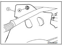
- Remove the push nut (A) from the expansion valve insulator (1) and reposition.
- Remove the bolt (A) that retains the low-pressure flexible hose and high-pressure pipe to the expansion valve.
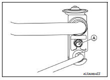
- Disconnect the low-pressure pipe and high-pressure pipe from the expansion valve.
- Remove the expansion valve bolts.
- Remove the expansion valve.
INSTALLATION
Installation is in the reverse order of removal.
CAUTION:
- Do not reuse O-rings.
- Apply A/C oil to the new expansion valve O-rings for installation.
- After charging refrigerant, check for leaks. Refer to HA-21, "Leak Test".
 Condenser
Exploded view
Core support upper cover
High-pressure pipe
High-pressure flexible hose
Refrigerant pressure sensor
Condenser and liquid tank assembly
Core support upper
Front
Conde ...
 Service data and specifications (SDS)
Service Data and Specification (SDS)
COMPRESSOR
OIL
REFRIGERANT
...
Other materials:
Removal and installation
Combination meter
Exploded view
Combination meter
Front cover
Removal and installation
Removal
Remove cluster lid a. Refer to ip-19, "removal and installation".
Remove the screws from the combination meter.
Remove the combination meter.
Disconnect the comb ...
Dtc/circuit diagnosis
Sport mode switch
Component function check
1. Check sport mode switch operation
Turn ignition switch on.
Check sport mode indicator lamp turns on/off on combination meter when
turn sport mode switch
on/off.
Is the inspection result normal?
Yes >> inspection end.
No >> ...
Engine control system
Symptom Table
SYSTEM � BASIC ENGINE CONTROL SYSTEM
1 - 6: The numbers refer to the order of inspection.
(continued on next table)
SYSTEM � ENGINE MECHANICAL & OTHER
1 - 6: The numbers refer to the order of inspection. ...
