Nissan Sentra Service Manual: Condenser
Exploded view
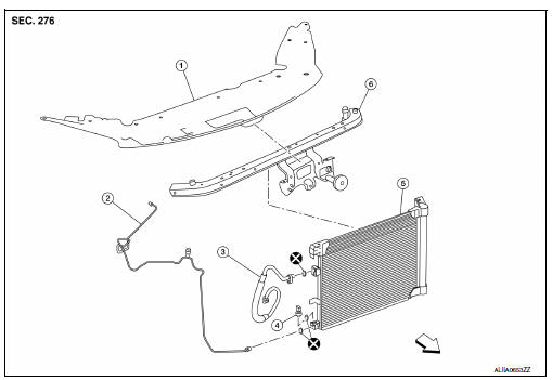
- Core support upper cover
- High-pressure pipe
- High-pressure flexible hose
- Refrigerant pressure sensor
- Condenser and liquid tank assembly
- Core support upper
 Front
Front
Condenser
Condenser : removal and installation
REMOVAL
- Discharge the refrigerant. Refer to HA-23, "Recycle Refrigerant".
- Reposition the hood lock assembly. Refer to DLK-154, "HOOD LOCK CONTROL : Exploded View".
NOTE:
Disconnection of the hood release cable is not necessary.
- Remove the core support upper. Refer to HA-39, "Exploded View".
- Remove the front grille. Refer to EXT-23, "Removal and Installation".
- Disconnect the harness connector from the refrigerant pressure sensor.
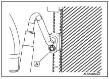
- Remove the bolt (A) that retains the high-pressure flexible hose to the condenser, then disconnect the high-pressure flexible hose from the condenser and liquid tank assembly.
CAUTION:
Cap or wrap the joint of the hose with suitable material such as vinyl tape to avoid the entry of air.
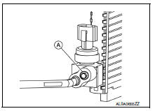
- Remove the bolt (A) that retains the high-pressure pipe to the condenser, then disconnect the high-pressure pipe from the condenser and liquid tank assembly.
- Remove the condenser and liquid tank assembly.
INSTALLATION
Installation is in the reverse order of removal.
CAUTION:
- Do not reuse O-rings.
- Apply A/C oil to the O-rings of the condenser for installation.
- After charging refrigerant, check for leaks. Refer to HA-21, "Leak Test".
Refrigerant pressure sensor
Refrigerant pressure sensor : removal and installation
REMOVAL
- Discharge the refrigerant. Refer to HA-23, "Recycle Refrigerant".
- Reposition the hood lock assembly. Refer to DLK-154, "HOOD LOCK CONTROL : Exploded View".
NOTE:
Disconnection of the hood release cable is not necessary.
- Remove the core support upper. Refer to HA-39, "Exploded View".
- Disconnect the harness connector from the refrigerant pressure sensor.
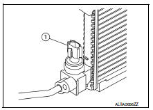
- Remove the refrigerant pressure sensor (1) from the liquid tank on the condenser.
CAUTION:
Do not damage the condenser fins.
INSTALLATION
Installation is in the reverse order of removal.
CAUTION:
- Do not reuse the O-ring.
- Apply A/C compressor oil to the new O-ring for installation.
- After charging refrigerant, check for leaks. Refer to HA-21, "Leak Test".
 Cooler pipe and hose
Exploded view
High-pressure service port
High-pressure pipe
Expansion valve
Low-pressure service port
Low-pressure flexible hose
Compressor
Refrigerant pressure sensor
Condenser ...
 Heating and cooling unit assembly
Exploded view
With air conditioning
Defroster seal
Center ventilator seal
Upper distribution module
Side ventilator seal (LH)
Blower motor
Blower unit
Intake door motor
Power tr ...
Other materials:
P0962 Pressure control solenoid A
DTC Logic
DTC DETECTION LOGIC
DTC
CONSULT screen terms
(Trouble diagnosis content)
DTC detection condition
Possible causes
P0962
PRESSURE CONTROL SOLENOID
A
(Pressure Control Solenoid A
Control Circuit Low)
The line pressure solenoid valve current is 200
...
P2014, P2016, P2017, P2018 Intake manifold runner control valve position
sensor
DTC Logic
DTC DETECTION LOGIC
NOTE:
If DTC P2014, P2016, P2017 or P2018 is displayed with DTC P0643, first
perform the trouble diagnosis
for DTC P0643. Refer to EC-353, "DTC Logic".
DTC No.
CONSULT screen terms
(Trouble diagnosis content)
DTC detecting condition
P ...
P2127, P2128 APP Sensor
DTC Logic
DTC DETECTION LOGIC
DTC No.
CONSULT screen terms
(Trouble diagnosis content)
DTC detecting condition
Possible cause
P2127
APP SEN 2/CIRC
(Throttle/Pedal position
sensor/switch “E” circuit
low)
An excessively low voltage from the APP
...
