Nissan Sentra Service Manual: Front combination lamp
Exploded View
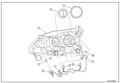
- Large cover (not serviceable)
- Small cover (not serviceable)
- Front combination lamp
- Halogen lamp bulb (high beam)
- Turn signal lamp bulb
- Turn signal lamp bulb socket
- LED harness connector
- Halogen lamp bulb (high beam) harness connector
- Halogen lamp bulb (low beam) harness connector
- Halogen lamp bulb (low beam)
- Side marker lamp bulb socket
- Side marker lamp bulb
Disassembly and Assembly
DISSASSEMBLY
WARNING:
Do not touch bulb while it is lit or right after being turned off. Burning may result.
CAUTION:
- Do not touch glass surface of the bulb with bare hands or allow oil or grease to get on it to prevent damage to bulb.
- Do not leave the bulb out of the lamp reflector for a long time
because dust, moisture, smoke, etc.
may affect the performance of the lamp.
- Remove front combination lamp. Refer to EXL-119, "Removal and Installation".
- Rotate the covers counterclockwise and remove.
- Rotate the halogen lamp bulb (low beam) counterclockwise and remove.
- Disconnect the harness connector from the halogen lamp bulb (low beam) and remove.
- Rotate the halogen lamp bulb (high beam) counterclockwise and remove.
- Disconnect the harness connector from the halogen lamp bulb (high beam) and remove.
- Rotate the side marker bulb socket counterclockwise and remove.
- Remove the side marker bulb from the side marker bulb socket.
- Rotate the turn signal bulb socket counterclockwise and remove.
- Remove the turn signal bulb from the turn signal bulb socket.
- Disconnect the harness connector from the LED circuit board and remove the harness.
ASSEMBLY
Assembly is in the reverse order of disassembly.
CAUTION:
After installing, be sure to install the bulb sockets securely to ensure watertightness.
Revision:

 Rear combination lamp
Exploded View
Rear combination lamp
Rear turn signal lamp bulb
Rear turn signal lamp socket
LED lamp harness connector
Rear combination lamp harness
connector
Back-up lamp bulb s ...
Other materials:
Tilt operation
Pull the lock lever down 1 and adjust the steering
wheel up or down 2 to the desired position.
Push the lock lever up 1 firmly to lock the
steering wheel in place.
WARNINGDo not adjust the steering wheel while
driving. You could lose control of your
vehicle and cause an accide ...
Power supply and ground circuit
WITH INTELLIGENT KEY SYSTEM
WITH INTELLIGENT KEY SYSTEM : Diagnosis Procedure
Regarding Wiring Diagram information, refer to BCS-51, "Wiring Diagram".
1.Check fuses and fusible link
Check that the following fuses and fusible link are not blown.
Is the fuse blown?
Yes >> r ...
Precaution for Supplemental Restraint System (SRS) "AIR BAG" and "SEAT
BELT PRE-TENSIONER"
The Supplemental Restraint System such as “AIR BAG” and “SEAT BELT PRE-TENSIONER”,
used along
with a front seat belt, helps to reduce the risk or severity of injury to the
driver and front passenger for certain
types of collision. Information necessary to service the system ...
