Nissan Sentra Service Manual: Ducts and grilles
Exploded View
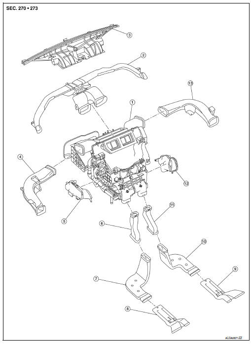
- Heating and cooling unit assembly
- Center ventilator duct
- Defroster duct
- Side ventilator duct (LH)
- Front floor duct (LH)
- Rear floor connecting duct (LH)
- Rear floor duct (LH)
- Rear floor duct nozzle (LH)
- Rear floor duct nozzle (RH)
- Rear floor duct (RH)
- Rear floor connecting duct (LH)
- Front floor duct (RH)
- Side ventilator duct (RH)
Defroster nozzle
DEFROSTER NOZZLE : Removal and Installation
REMOVAL
- Remove the side defroster ducts (LH/RH). Refer to VTL-7, "SIDE VENTILATOR DUCT : Removal and Installation".
- Remove the defroster nozzle screws.
- Remove the defroster nozzle.
INSTALLATION
Installation is in the reverse order of removal.
Center ventilator duct
CENTER VENTILATOR DUCT : Removal and Installation
REMOVAL
- Remove the instrument panel assembly. Refer to IP-14, "Removal and Installation".
- Remove the center ventilator duct screws.
- Remove the center ventilator duct.
INSTALLATION
Installation is in the reverse order of removal.
Side ventilator duct
SIDE VENTILATOR DUCT : Removal and Installation
REMOVAL
- Remove the instrument panel assembly. Refer to IP-14, "Removal and Installation".
- Remove the side ventilator duct screws.
- Release the side ventilator duct from the defroster duct and remove.
INSTALLATION
Installation is in the reverse order of removal.
Rear floor duct
REAR FLOOR DUCT : Removal and Installation - Rear Floor Connecting Duct
REMOVAL
- Remove the center console side finisher. Refer to IP-17, "Exploded View".
- Remove the rear floor connecting duct (LH/RH).
INSTALLATION
Installation is in the reverse order of removal.
REAR FLOOR DUCT : Removal and Installation - Rear Floor Duct
REMOVAL
- Remove the front floor trim. Refer to INT-35, "Removal and Installation".
- Remove the floor insulator
- Release the rear floor duct nozzle from the rear floor duct and remove.
INSTALLATION
Installation is in the reverse order of removal.
REAR FLOOR DUCT : Removal and Installation - Rear Floor Duct Nozzle
REMOVAL
- Remove the rear floor duct. Refer to VTL-8, "REAR FLOOR DUCT : Removal and Installation - Rear Floor Duct Nozzle".
- Remove the rear floor duct nozzle (LH/RH).
INSTALLATION
Installation is in the reverse order of removal.
Exploded View
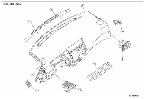
- Instrument panel assembly
- Defroster grille (RH)
- Defroster grille (LH)
- Side defroster grille (LH)
- Side ventilator grille (LH)
- Center ventilator grille
- Side ventilator grille (RH)
- Side defroster grille (RH)
Defroster grille
DEFROSTER GRILLE : Removal and Installation
REMOVAL
- Release the defroster grille pawls using a suitable tool.
- Remove the defroster grille (LH/RH).
INSTALLATION
Installation is in the reverse order of removal.
Center ventilator grille
CENTER VENTILATOR GRILLE : Removal and Installation
REMOVAL
- Remove cluster lid C. Refer to IP-20, "Removal and Installation - Cluster Lid C".
- Release the center ventilator grille pawls using a suitable tool.
- Remove the center ventilator grille (LH/RH).
INSTALLATION
Installation is in the reverse order of removal.
Side ventilator grille
SIDE VENTILATOR GRILLE : Removal and Installation
REMOVAL
- Remove the instrument side finisher. Refer to IP-14, "Exploded View".
- Remove the side ventilator grille screw (A).
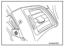
- Remove the side ventilator grille (LH/RH).
INSTALLATION
Installation is in the reverse order of removal.
Side defroster grille
SIDE DEFROSTER GRILLE : Removal and Installation
REMOVAL
- Remove the center ventilator duct. Refer to VTL-7, "CENTER VENTILATOR DUCT : Removal and Installation".
- Release the side defroster grille pawl using a suitable tool.
- Remove the side defroster grille (LH/RH).
INSTALLATION
Installation is in the reverse order of removal.

 Blower motor
Exploded View
Heating and cooling unit assembly
Blower motor
Front
Removal and Installation
Remove the glove box assembly. Refer to IP-22, "Removal and
Installation".
...
Other materials:
Basic inspection
Diagnosis and repair workflow
Work flow
Overall sequence
Detailed flow
1.Obtain information about symptom
Interview the customer to obtain as much information as possible about the
conditions and environment under
which the malfunction occurred.
>> GO TO 2.
2.Check symptom
...
Starting the engine
Apply the parking brake.
CVT model:
Move the shift lever to P (Park) or N (Neutral).
P (Park) is recommended.
The shift lever cannot be moved out of
P (Park) and into any of the other gear
positions if the ignition switch is
turned to the OFF position or if the key
is removed from th ...
Specifications
Engine
This spark ignition system complies with the Canadian standard ICES-002.
Wheels and tires
Dimensions and weights
...
