Nissan Sentra Service Manual: Basic inspection
Diagnosis and repair workflow
Work flow
Overall sequence
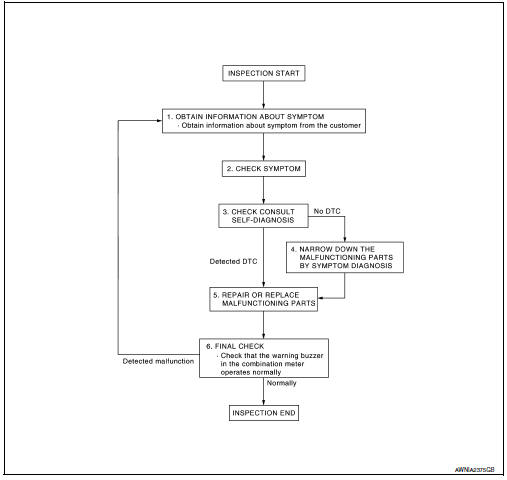
Detailed flow
1.Obtain information about symptom
Interview the customer to obtain as much information as possible about the conditions and environment under which the malfunction occurred.
>> GO TO 2.
2.Check symptom
- Check the symptom based on the information obtained from the customer.
- Check if any other malfunctions are present.
>> Go to 3.
3.Check consult self-diagnosis results
Connect consult and perform self-diagnosis. Refer to mwi-26, "dtc index".
Are self-diagnosis results normal? Yes >> go to 4.
No >> go to 5.
4.Narrow down malfunctioning parts by symptom diagnosis
Perform symptom diagnosis and narrow down the malfunctioning parts.
>> Go to 5.
5.Repair or replace malfunctioning parts
Repair or replace malfunctioning parts.
Note:
If dtc is displayed, erase dtc after repairing or replacing malfunctioning parts.
>> Go to 6.
6.Final check
Check that the warning buzzer in the combination meter operates normally.
Does it operate normally? Yes >> inspection end.
No >> go to 1.
 Wiring diagram
Meter system
Wiring diagram
Compass
Wiring diagram
...

Other materials:
Ecm branch line circuit
Diagnosis Procedure
1.CHECK CONNECTOR
Turn the ignition switch OFF.
Disconnect the battery cable from the negative terminal.
Check the terminals and connectors of the ECM for damage, bend and loose
connection (unit side and
connector side).
Is the inspection result normal?
YES > ...
System
Body control system
Body control system : system description
OUTLINE
BCM (Body Control Module) controls the various electrical components. It
inputs the information required to
the control from CAN communication and the signal received from each switch
and sensor.
BCM has combination ...
Normal operating condition
Compass
Compass : description
Compass
The electronic compass is highly protected from changes in most magnetic
fields. However, some large
changes in magnetic fields can affect it. Some examples are (but not limited
to): high tension power lines,
large steel buildings, subways, steel ...
