Nissan Sentra Service Manual: Drive plate
Exploded View
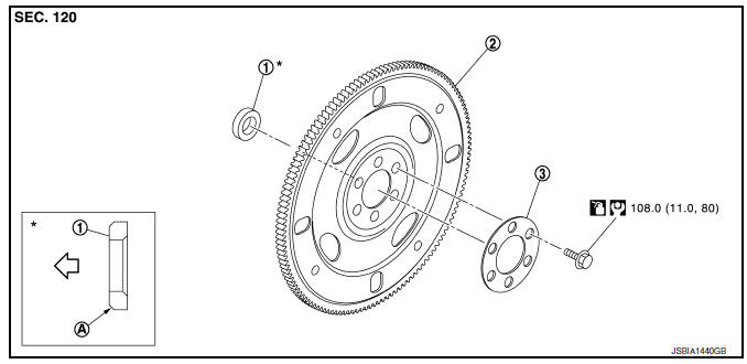
- Pilot converter
- Drive plate
- Reinforcement plate
- Chamfered
Removal and Installation
REMOVAL
- Remove the engine and the transaxle assembly from the vehicle, and separate the transaxle from the engine. Refer to EM-86, "CVT : Exploded View".
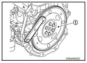
- Remove drive plate.
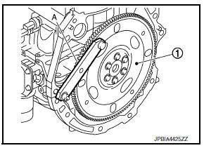
- Secure drive plate (1) using Tool (A), and remove bolts using suitable tool.
Tool number : KV11105210 (J-44716)
Tool number : KV11105210 (J-44716)
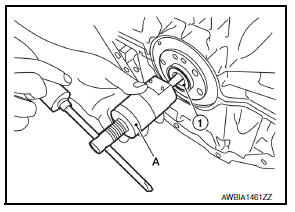
- Remove pilot converter (1), from the rear end of the crankshaft.
Use Tool (A), if necessary.
Tool number : ST16610000 (J-23907)
INSTALLATION
- Install pilot converter (1), drive plate (2) and reinforcement plate (3) as shown.
(A) : Crankshaft rear end
(B) : Rounded
- Using a drift of 33 mm (1.30 in) in diameter, press-fit pilot converter into the end of crankshaft until it stops.
- Install drive plate.
- Secure drive plate (1) using Tool (A), and install bolts using suitable tool.
Tool number : KV11105210 (J-44716)
CAUTION:
Be careful not to damage or scratch contact surface.
Inspection
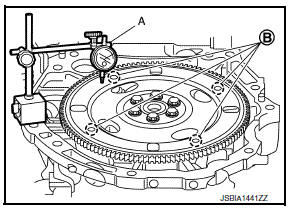
DRIVE PLATE DEFLECTION
- Measure the deflection of drive plate contact surface to torque converter with a dial indicator (A).
- Measure the deflection at the area limited between 12.4 mm (0.488 in) dia and 20.0 mm (0.787 in) dia around hole (B).
Limit : 0.35 mm (0.0138 in) or less.
- If measured value is out of the standard, replace drive plate.
 Flywheel
Exploded View
Flywheel
Removal and Installation
REMOVAL
Remove the engine and the transaxle assembly from the vehicle, and
separate the transaxle from the
engine. Refer to TM-28, ...
 Cylinder block
Exploded View
Cylinder block
Block heater (for Canada)
Top ring
Second ring
Oil ring
Piston
Piston pin
Snap ring
Connecting rod
Connecting rod bearing (upper)
Connecting r ...
Other materials:
Rear seat
Exploded View
Rear seatback assembly (rh)
Seatback striker
Seatback latch release knob
Seatback latch assembly
Seatback silencer (RH)
Rear seatback frame (rh)
Seatback latch release knob finisher
Rear seat bolster trim (RH)
Rear seat bolster pad (RH)
Rear seat bolster (rh)
...
Steering wheel turning force is heavy or light
Description
Steering wheel turning force is heavy or light.
Diagnosis Procedure
1.PERFORM SELF-DIAGNOSIS
With CONSULT
Turn the ignition switch OFF to ON.
Perform EPS self-diagnosis.
Is any DTC detected?
YES >> Check the DTC. Refer to STC-14, "DTC Index".
NO & ...
System description
Component parts
Component parts location
Front tweeter LH
Steering switches
Audio unit
Front tweeter rh
Microphone
Front door speaker lh
Front door speaker rh
Rear speaker rh
Rear speaker lh
Antenna amp.
Satellite antenna
Window antenna
Usb interface
BluetoothВ® ...
