Nissan Sentra Service Manual: Description
| Number | Item | Description |
| 1 | Power supply |
|
| 2 | Fusible link |
|
| 3 | Number of fusible link/ fuse |
|
| 4 | Fuse |
|
| 5 | Current rating of fusible link/fuse |
|
| 6 | Optional splice |
|
| 7 | Connector number |
|
| 8 | Splice |
|
| 9 | Page crossing |
|
| 10 | Option abbreviation |
|
| 11 | Relay |
|
| 12 | Option description |
|
| 13 | Switch |
|
| 14 | Circuit (Wiring) |
|
| 15 | System branch |
|
| 16 | Shielded line |
|
| 17 | Component name |
|
| 18 | Ground (GND) |
|
| 19 | Connector |
|
| 20 | Connectors |
|
| 21 | Wire color |
|
| B = Black W = White R = Red G = Green L = Blue Y = Yellow LG = Light Green BG = Beige BR = Brown LA = Lavender OR or O = Orange P = Pink PU or V (Violet) = Purple GY or GR = Gray SB = Sky Blue CH = Dark Brown DG = Dark Green |
||
|
||
| 22 | Terminal number |
|

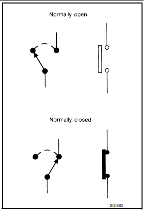
 –≤–Ç—ú.
Switch positions
Switches are shown in wiring diagrams as if the vehicle is in the –≤–Ç—önormal–≤–Ç—ú condition.
A vehicle is in the –≤–Ç—önormal–≤–Ç—ú condition when:
- ignition switch is –≤–Ç—öOFF–≤–Ç—ú,
- doors, hood and trunk lid/back door are closed,
- pedals are not depressed, and
- parking brake is released.
Multiple switch
The continuity of multiple switch is described in two ways as shown below.
- The switch chart is used in schematic diagrams.
- The switch diagram is used in wiring diagrams.
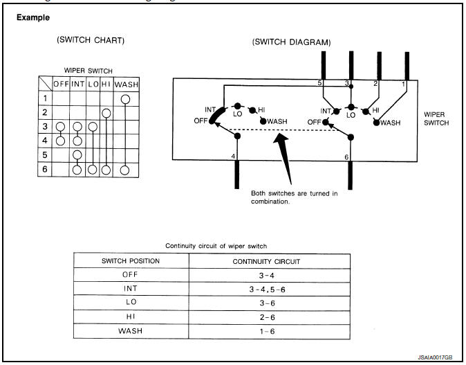
 Sample/wiring diagram -example-
For detail, refer to following GI-11, "Description".
...
 Abbreviations
Abbreviation List
The following ABBREVIATIONS are used:
A
ABBREVIATION
DESCRIPTION
A/C
Air conditioner
A/C
Air conditioning
A/F sensor
Air fuel ...
Other materials:
Headlining
Exploded View
STANDARD ROOF
Headlining
Assist grip
Map lamp bracket
Sun visor (RH)
Sun visor cover
Sun visor holder
Map lamp
Sun visor (LH)
Interior room lamp
Assist grip cap
Headlining clip
Metal clip
Pawl
Metal clip
Sunroof
Headlining
Assist grip
...
Periodic maintenance
CVT FLUID
Inspection
FLUID LEAKAGE
Check transaxle surrounding area (oil seal and plug etc.) for fluid
leakage.
If anything is found, repair or replace damaged parts and adjust
CVT fluid level. Refer to TM-251, "Adjustment".
Replacement
CVT fluid : Refer to TM-288, & ...
Moonroof (if so equipped)
Power moonroof
The moonroof will only operate when the ignition
switch is placed in the ON position. The power
moonroof is operational for a period of time, even
if the ignition switch is placed in the ACC or OFF
position. If the driver’s door or the front passenger’s
door is opened du ...
