
Nissan Sentra Service Manual: Control cable
Exploded View
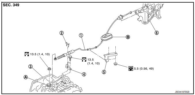
- Control cable
- Lock plate
- Transaxle assembly
- Bracket A
- Bracket B
- CVT shift selector assembly
- Manual lever
- Grommet
Removal and Installation
INSTALLATION
CAUTION:
Always apply the parking brake before performing removal and installation.
- Apply the parking brake.
CAUTION:
Make sure the vehicle cannot move with the parking brake applied.
- Remove the center console assembly. Refer to IP-17, "Removal and Installation".
- Move the shift selector to “P” position
- Remove the control cable from the shift selector assembly with the following procedure.
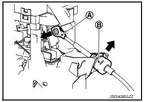
- Disconnect the tip (A) of control cable from the shift selector assembly.
- Remove socket (B) from shift selector assembly.
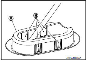
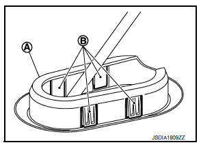
- Disengage the pawls (B) of the grommet (A), and pull downwards to remove.
- Remove the battery. Refer to PG-50, "Removal and Installation (Battery)".
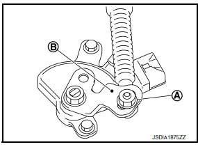
- Remove the control cable installation nut (A) from the manual lever (B).
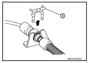
- Remove the lock plate (1).
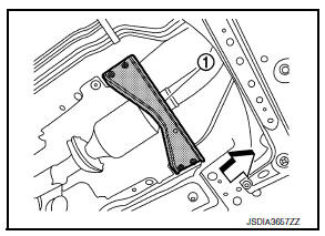
- Remove the tunnel stay (1).
 : Front
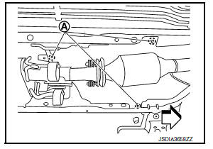
- Remove the exhaust front tube and sub muffler from the exhaust system. Refer to EX-5, "Removal and Installation".
- Remove the heat plate fixtures (A).
 : Front
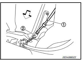
- Remove the control cable (1) from the bracket (2).
 : Front
- Remove the control cable from the vehicle.
INSTALLATION
Installation is in the reverse order of removal.
- From below the vehicle, press the grommet (A) into place until the pawls (B) make a click sound.
CAUTION:
- Place the grommet on the floor, then fasten it in place from below the vehicle.
- Check that pulling down on the grommet does not disconnect it.
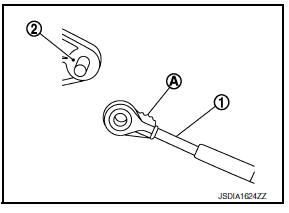
- Pay attention to the following when connecting the control cable to the shift selector.
- When connecting the control cable (1) to the shift selector assembly (2), face the grooved surface of the rib (A) up and insert the control cable until it stops.
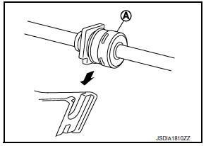
- Install the socket (A) onto the shift selector.
CAUTION:
- Place the socket onto the shift selector, then fasten it in place from above.
- Check that the pulling on the socket does not disconnect it.
Inspection and Adjustment
INSPECTION AND ADJUSTMENT
Check the CVT position. If a malfunction is found, adjust the CVT position. Refer to TM-150, "Inspection" (Inspection) or TM-150, "Adjustment" (Adjustment).
 CVT Shift selector
Exploded View
Shift selector knob
Lock pin
Knob cover
Position indication panel
Detent switch
Shift lock unit
Park position switch
Shift selector assembly
Shift selector harne ...
 Key interlock cable
Exploded View
Shift selector assembly
Clip
Key interlock cable
Clip
Key cylinder
Removal and Installation
REMOVAL
CAUTION:
Always apply the parking brake before performing remov ...
Other materials:
Vin registration
Description
VIN Registration is an operation to registering VIN in ECM. It must be
performed each time ECM is replaced.
NOTE:
Accurate VIN which is registered in ECM may be required for Inspection &
Maintenance (I/M).
Work Procedure
1.CHECK VIN
Check the VIN of the vehicle and note it. ...
P0137 HO2S2
DTC Logic
DTC DETECTION LOGIC
The heated oxygen sensor 2 has a much longer switching time
between rich and lean than the air fuel ratio (A/F) sensor 1. The oxygen
storage capacity of the three way catalyst (manifold) causes the
longer switching time. To judge the malfunctions of heated oxygen
...
Parking brake system
Inspection and Adjustment
INSPECTION
Lever Stroke
Operate the parking brake lever with a force of 196 N (20.0
kg-f, 44.1 lb-f). Check that the lever stroke is
within the specified number of notches. (Check it by listening to the clicks
of the ratchet.)
Number of notches : Refer t ...
