Nissan Sentra Service Manual: Main line between ipdm-e and dlc circuit
Diagnosis procedure
1.Check connector
- Turn the ignition switch off.
- Disconnect the battery cable from the negative terminal.
- Check the following terminals and connectors for damage, bend and loose connection (connector side and harness side).
- Harness connector e4
- Harness connector m2
Is the inspection result normal? YES >> GO TO 2.
NO >> Repair the terminal and connector.
2.Check harness continuity (open circuit)
- Disconnect the following harness connectors.
- IPDM E/R
- Harness connectors e4 and m2
- Check the continuity between the IPDM E/R harness connector and the harness connector.
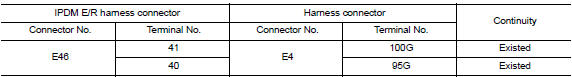
Is the inspection result normal? YES >> GO TO 3.
NO >> Repair the main line between the IPDM E/R and the harness connector E4.
3.Check harness continuity (open circuit)
Check the continuity between the harness connector and the data link connector.
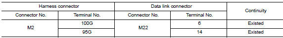
Is the inspection result normal? Yes (present error)>>check can system type decision again.
Yes (past error)>>error was detected in the main line between the ipdm e/r and the data link connector.
No >> repair the main line between the harness connector m2 and the data link connector.
 Can system (type 4)
Dtc/circuit diagnosis ...
 Main line between dlc and hvac circuit
Diagnosis Procedure
1.Check harness continuity (open circuit)
Turn the ignition switch OFF.
Disconnect the battery cable from the negative terminal.
Disconnect the following harness connector ...
Other materials:
C1115 ABS Sensor [abnormal signal]
DTC Logic
DTC DETECTION LOGIC
DTC
Display Item
Malfunction detected condition
Possible causes
C1115
ABS SENSOR
[ABNORMAL SIGNAL]
When difference in wheel speed between any wheel
and others is detected while the vehicle is driven, because
of installation of t ...
Ignition switch (if so equipped)
WARNING
Never remove or turn the key to the
LOCK position while driving. The steering
wheel will lock (for models with a
steering lock mechanism). This may
cause the driver to lose control of the
vehicle and could result in serious vehicle
damage or personal injury ...
Basic inspection
Diagnosis and repair work flow
Work flow
Detailed flow
1.Obtain information about symptom
Interview the customer to obtain as much information as possible about the
conditions and environment under
which the malfunction occurs.
>> GO TO 2.
2.Check symptom
Check the symptom based ...
