Nissan Sentra Service Manual: Consult function
FUNCTION
| Diagnostic test mode | Function |
| Self Diagnostic Results | Self-diagnostic results such as 1st trip DTC, DTCs and 1st trip freeze frame data or freeze frame data can be read and erased quickly.* |
| Data Monitor | Input/Output data in the ECM can be read. |
| Work Support | This mode enables a technician to adjust some devices faster and more accurately by following the indications on the CONSULT unit. |
| Active Test | Diagnostic Test Mode in which CONSULT drives some actuators apart from the ECMs and also shifts some parameters in a specified range. |
| Ecu Identification | ECM part number can be read. |
| DTC Work Support | The use of this mode enables quick and accurate performance of Confirmation Procedure. |
*: The following emission-related diagnostic information is cleared when the ECM memory is erased.
- Diagnostic trouble codes
- 1st trip diagnostic trouble codes
- Freeze frame data
- 1st trip freeze frame data
- System readiness test (SRT) codes
- Test values
SELF DIAGNOSTIC RESULTS MODE
Self Diagnostic Item
Regarding items of DTC and 1st trip DTC, refer to EC-94, "DTC Index".
How to Read DTC and 1st Trip DTC
DTCs and 1st trip DTCs related to the malfunction are displayed in “Self-diag results”.
- When ECM detects a 1st trip DTC, “1t” is displayed for “TIME”.
- When ECM has detected a current DTC, “0” is displayed for “TIME”.
- If “TIME” is neither “0” nor “1t”, the DTC occurred in the past and ECM shows the number of times the vehicle has been driven since the last detection of the DTC.
How to Erase DTC and 1st Trip DTC
NOTE:
- If the ignition switch stays ON after repair work, be sure to turn ignition switch OFF once. Wait at least 10 seconds and then turn it ON (engine stopped) again.
- If the DTC is not for CVT related items (see EC-94, "DTC Index"), skip step 1.
- Erase DTC in TCM. Refer to TM-105, "Description".
- Select “ENGINE” using CONSULT.
- Select “SELF-DIAG RESULTS”.
- Touch “ERASE”. (DTC in ECM will be erased.)
Freeze Frame Data and 1st Trip Freeze Frame Data
| Freeze frame data item* | Description |
| DIAG TROUBLE CODE [PXXXX] | The engine control component part/control system has a trouble code the is displayed as PXXXX. (Refer to EC-94, "DTC Index".) |
| FUEL SYS-B1 |
Mode2: Open loop due to detected system malfunction Mode3: Open loop due to driving conditions (power enrichment, deceleration enleanment) Mode4: Closed loop - using oxygen sensor(s) as feedback for fuel control Mode5: Open loop - has not yet satisfied condition to go to closed loop |
| CAL/LD VALUE [%] | The calculated load value at the moment a malfunction is detected is displayed. |
| COOLANT TEMP [В°C] or [В°F] | The engine coolant temperature at the moment a malfunction is detected is displayed. |
| L-FUEL TRM-B1 [%] |
|
| S-FUEL TRM-B1 [%] |
|
| ENGINE SPEED [rpm] | The engine speed at the moment a malfunction is detected is displayed. |
| VEHICL SPEED [km/h] or [mph] | The vehicle speed at the moment a malfunction is detected is displayed. |
| ABSOL THВ·P/S [%] | The throttle valve opening angle at the moment a malfunction is detected is displayed. |
| B/FUEL SCHDL [msec] | The base fuel schedule at the moment a malfunction is detected is displayed. |
| INT/A TEMP SE [В°C] or [В°F] | The intake air temperature at the moment a malfunction is detected is displayed. |
| FUEL SYS-B2 | These items are displayed but are not applicable to this model. |
| L-FUEL TRM-B2 [%] | |
| S-FUEL TRM-B2 [%] | |
| INT MANI PRES [kPa] | |
| CONBUST CONDITION |
*: The items are the same as those of 1st trip freeze frame data.
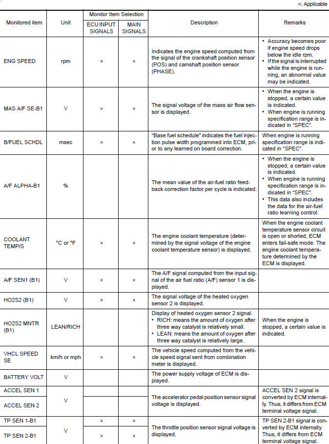
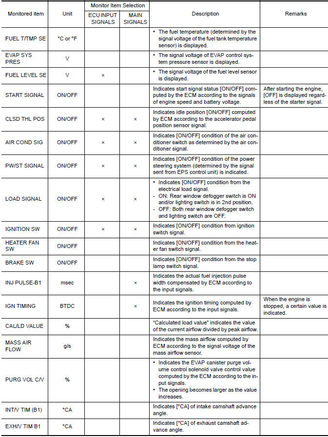
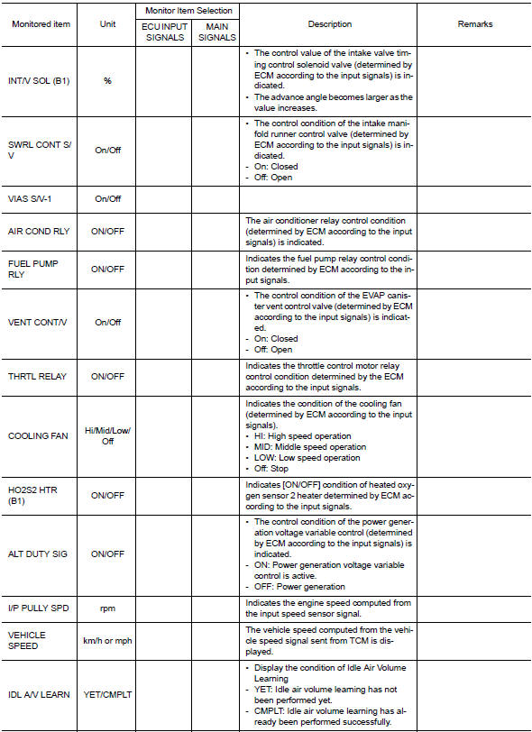
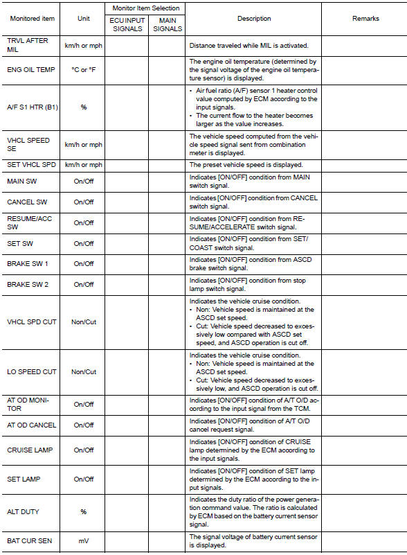
DATA MONITOR MODE
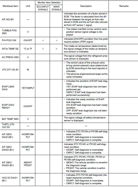
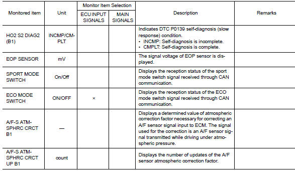
Monitored Item
NOTE:
- The following table includes information (items) inapplicable to this vehicle. For information (items) applicable to this vehicle, refer to CONSULT display items.
- For reference values of the following items, refer to EC-77, "Reference Value".
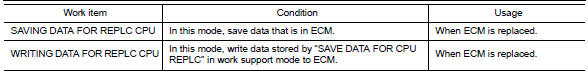
Work support mode
Work Item
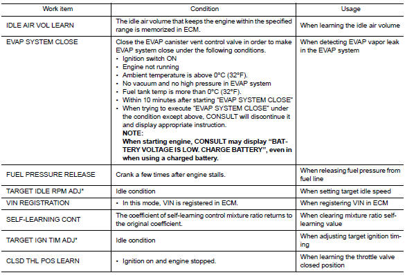
*: This function is not necessary in the usual service procedure.
Active test mode
Test Item

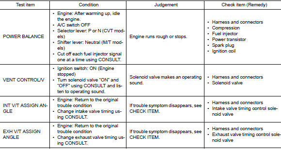
*: Leaving cooling fan OFF with CONSULT while engine is running may cause the engine to overheat.
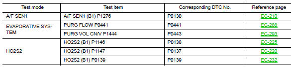
Dtc work support mode
SRT & P-DTC MODE
SRT STATUS Mode
- For items whose SRT codes are set, “CMPLT” is displayed on the CONSULT screen; for items whose SRT codes are not set, “INCMP” is displayed.
- “SRT STATUS” provides the presence or absence of permanent DTCs stored in ECM memory.
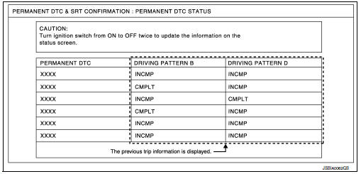
PERMANENT DTC STATUS Mode
How to display permanent DTC status
- Turn ignition switch OFF and wait at least 10 seconds.
- Turn ignition switch ON.
- Turn ignition switch OFF and wait at least 10 seconds.
- Turn ignition switch ON.
- Select “PERMANENT DTC STATUS” in “DTC & SRT CONFIRMATION” mode with CONSULT.
NOTE:
Permanent DTCs stored in ECM memory are displayed on the CONSULT screen to show if a driving pattern required for erasing permanent DTCs is complete (CMPLT) or incomplete (INCMP).
CAUTION:
Since the “PERMANENT DTC STATUS” screen displays the previous trip information, repeat the following twice to update the information: “Ignition switch OFF”, “Wait for more than 10 seconds” and “Ignition switch ON”.
NOTE:
This mode is not used in regions that permanent DTCs are not regulated by law.
SRT WORK SUPPORT Mode
This mode enables a technician to drive a vehicle to set the SRT while monitoring the SRT status.
PERMANENT DTC WORK SUPPORT Mode
This mode enables a technician to drive a vehicle to complete the driving pattern that is required for erasing permanent DTC.
NOTE:
This mode is not used in regions that permanent DTCs are not regulated by law.
 On board diagnosis function
ON BOARD DIAGNOSIS ITEM
The on board diagnostic system has the following functions.
Diagnostic test mode
Function
Bulb check
MIL can be checked.
SRT status
ECM can ...
 Ecu diagnosis information
ECM
Reference Value
VALUES ON THE DIAGNOSIS TOOL
NOTE:
The following table includes information (items) inapplicable to this
vehicle. For information (items) applicable
to this vehicle, re ...
Other materials:
Recommended fluids and lubricants
Fluids and lubricants
*1: For additional information, see “engine oil recommendation”.
*2: As an alternative to this recommended oil, sae 5w-30 conventional
petroleum based oil may be used and meet all specifications
and requirements necessary to maintain the new vehicle limited ...
Repairing material
Foam Repair
During factory assembly, foam insulators are installed in certain body panels
and locations around the vehicle.
Use the following procedure(s) to replace any factory-installed foam insulators.
URETHANE FOAM APPLICATIONS
Use commercially available Urethane foam for sealant (foam m ...
Precaution for supplemental restraint system (srs) "air bag" and "seat belt
pre-tensioner"
The Supplemental Restraint System such as “AIR BAG” and “SEAT BELT PRE-TENSIONER”,
used along
with a front seat belt, helps to reduce the risk or severity of injury to the
driver and front passenger for certain
types of collision. Information necessary to service the system ...
