Nissan Sentra Service Manual: Center console assembly
Exploded View
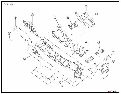
- Center console upper finisher
- Center console side finisher (RH)
- Center console side finisher (LH)
- Center console side finisher screw cover (LH/ RH)
- Center console assembly
- Center console screw cover (LH/ RH)
- Center console rear finisher
- Center console rear finisher cover
- Center console coin tray (if equipped)
- Heated seat switch finisher (if equipped)
- Center console cup holder finisher
- Shift selector finisher
- Storage bin
Removal and Installation
REMOVAL
- Remove the center console side finishers (1) (LH/RH).
- Remove the center console side finisher screw (A) (LH/RH).
- Release the clips using a suitable tool, then remove the center console side finisher.
 Metal clip
- Remove the shift selector finisher (1).
- Remove cluster lid C lower. Refer to IP-20, "Removal and Installation - Cluster Lid C Lower".
- Remove the shift selector screws (A).
- Release the clips using a suitable tool, then remove the shift selector finisher.
 Metal clip
- Release the center console cup holder finisher clips, then remove the center console cup holder finisher (1).
 Metal clip
- Remove the center console screw cover (1) using a suitable tool and the center console screws (A) (LH/RH).
- Remove the remaining center console screws (A).
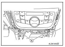
- Disconnect the harness connectors from the center console assembly and remove.
INSTALLATION
Installation is in the reverse order of removal.
 Steering column covers
Removal and Installation
REMOVAL
Remove the steering column cover screws (A), then remove the
steering column upper (1) and lower (2) covers.
NOTE:
Shown with steering wheel removed for ...
 Cluster lid A
Removal and Installation
REMOVAL
Release cluster lid A clips and pawls using a suitable tool.
: Pawl
Metal clip
Remove cluster lid A.
INSTALLATION
Installation is in the reverse ...
Other materials:
Brake booster
Inspection
Operation
Depress the brake pedal several times at five second intervals with
the engine stopped. Start the engine with the brake pedal fully
depressed. Check that the clearance between brake pedal and dash
lower panel decreases.
NOTE:
A slight impact with a small click may be felt ...
Dtc/circuit diagnosis
U1000 can comm circuit
Description
Refer to LAN-7, "CAN COMMUNICATION SYSTEM : System Description".
Dtc logic
Dtc detection logic
Consult display
Dtc detection condition
Possible cause
Can comm circuit
[u1000]
When ipdm e/r cannot communicate with can comm ...
Main line between dlc and hvac circuit
Diagnosis Procedure
1.Check harness continuity (open circuit)
Turn the ignition switch OFF.
Disconnect the battery cable from the negative terminal.
Disconnect the following harness connectors.
Ecm
A/c auto amp.
Check the continuity between the data link connector and the a/c ...
