Nissan Sentra Service Manual: C1111 PUMP MOTOR
DTC Logic
DTC DETECTION LOGIC
| DTC | Display Item | Malfunction detected condition | Possible causes |
| C1111 | PUMP MOTOR |
|
|
DTC CONFIRMATION PROCEDURE
1.CHECK SELF DIAGNOSTIC RESULT
 With CONSULT
-
Turn ignition switch OFF.
-
Depress brake pedal 20 times or more.
-
Start the engine and wait for 3 minutes or more.
-
Perform self diagnostic result.
Is DTC C1111 detected? YES >> Proceed to diagnosis procedure. Refer to BRC-65, "Diagnosis Procedure".
NO >> Inspection End.
Diagnosis Procedure
Regarding Wiring Diagram information, refer to BRC-44, "Wiring Diagram".
1.CONNECTOR INSPECTION
-
Turn ignition switch OFF.
-
Disconnect ABS actuator and electric unit (control unit) connectors.
-
Check connectors and terminals for deformation, disconnection, looseness or damage.
Is the inspection result normal? YES >> GO TO 2.
NO >> Repair or replace as necessary.
2.Check abs motor and motor relay battery power supply
Check voltage between ABS actuator and electric unit (control unit) connector E33 terminal 1 and ground.
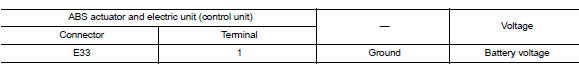
Is the inspection result normal? YES >> GO TO 3.
NO >> Repair or replace malfunctioning components.
3.Check ABS Actuator and electric unit (control unit) ground circuit
Check continuity between ABS actuator and electric unit (control unit) connector E33 terminals 13, 38 and ground.
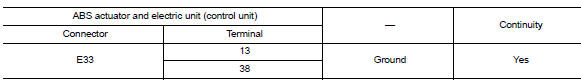
Is the inspection result normal? YES >> Replace ABS actuator and electric unit (control unit). Refer to BRC-110, "Removal and Installation".
NO >> Repair or replace malfunctioning components.
 1110, C1170 ABS Actuator and electric unit (control unit)
DTC Logic
DTC DETECTION LOGIC
DTC
Display item
Malfunction detected condition
Possible cause
C1110
CONTROLLER FAILURE
When there is an internal malfunction in the ABS ...
 C1113, C1145, C1146 Yaw rate/side/decel G Sensor
DTC Logic
DTC DETECTION LOGIC
DTC
Display Item
Malfunction detected condition
Possible causes
C1113
G SENSOR
When a malfunction is detected in longitunal G sensor
s ...
Other materials:
Service data and specifications (SDS)
Steering Wheel
Steering Angle
Steering Column
STEERING COLUMN LENGTH
TILT MECHANISM OPERATING RANGE
Power Steering Gear
STEERING OUTER SOCKET AND INNER SOCKET
RACK STROKE
...
Removal and installation
Hood
Hood assembly
Hood assembly : exploded view
Hood hinge (LH/RH)
Hood assembly
Hood bumper rubber
Hood seal
Hood insulator
Hood support rod
Hood support rod clamp
Clip
Hood assembly : removal and installation
CAUTION:
Use two people when removing or installing h ...
DTC/circuit diagnosis
U1000 CAN COMM CIRCUIT
Description
CAN (Controller Area Network) is a serial communication system for real time
application. It is an on-vehicle
multiplex communication system with high data communication speed and excellent
error detection ability.
Many electronic control units are equip ...
