Nissan Sentra Service Manual: Basic inspection
Diagnosis and repair workflow
Work flow
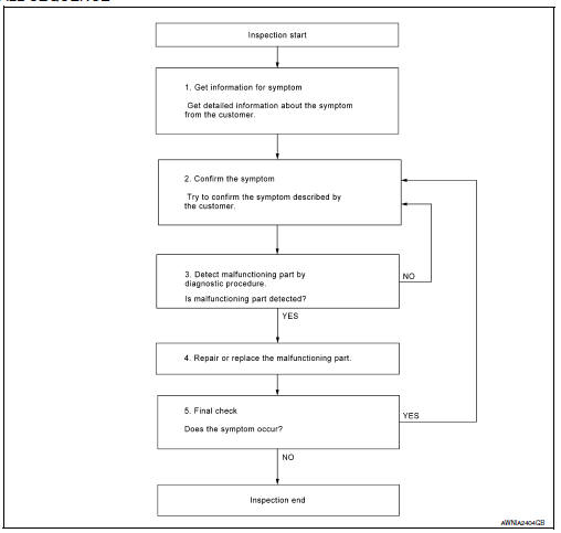
OVERALL SEQUENCE
DETAILED FLOW
1.GET INFORMATION FOR SYMPTOM
Get detailed information from the customer about the symptom (the condition and the environment when the incident/malfunction occurred).
>> GO TO 2
2.CONFIRM THE SYMPTOM
Try to confirm the symptom described by the customer. Verify relation between the symptom and the condition when the symptom is detected. Refer to AV-285, "Symptom Table".
>> GO TO 3
3.DETECT MALFUNCTIONING PART BY DIAGNOSTIC PROCEDURE
Inspect according to Diagnostic Procedure of the system.
Is malfunctioning part detected? YES >> GO TO 4
NO >> GO TO 2
4.REPAIR OR REPLACE THE MALFUNCTIONING PART
- Repair or replace the malfunctioning part.
- Reconnect parts or connectors disconnected during Diagnostic Procedure.
>> GO TO 5
5.FINAL CHECK
Refer to confirmed symptom in step 2, and make sure that the symptom is not detected.
Was the repair confirmed? YES >> Inspection End.
NO >> GO TO 2
Inspection and adjustment
Additional service when replacing av control unit
Additional service when replacing av control unit : description
BEFORE REPLACEMENT
When replacing AV control unit, save or print current vehicle specification with CONSULT configuration before replacement.
NOTE:
If “Before Replace ECU” cannot be used, use the “After Replace ECU” or “Manual Configuration” after replacing AV control unit.
AFTER REPLACEMENT
CAUTION:
When replacing AV control unit, you must perform “After Replace ECU” with CONSULT.
- Complete the procedure of “After Replace ECU” in order.
- If you set incorrect “After Replace ECU”, incidents might occur.
- Configuration is different for each vehicle model. Confirm configuration of each vehicle model.
Additional service when replacing av control unit : work procedure
1.SAVING VEHICLE SPECIFICATION
 CONSULT
Enter “Re/Programming, Configuration” and perform “Before Replace ECU” to save or print current vehicle specification.
NOTE:
If “Before Replace ECU” cannot be used, use the “After Replace ECU” or “Manual Configuration” after replacing AV control unit.
>> GO TO 2.
2.REPLACE AV CONTROL UNIT
Replace AV control unit. Refer to AV-298, "Removal and Installation".
>> GO TO 3.
3.WRITING VEHICLE SPECIFICATION
 CONSULT
- Enter "Re/Programming, Configuration".
- If “Before Replace ECU” operation was performed, automatically an "Operation Log Selection" screen will be displayed. Select the applicable file from the "Saved Data List" and press “Confirm” to write vehicle specification. Refer to AV-251, "CONFIGURATION (AV CONTROL UNIT) : Work Procedure".
- If “Before Replace ECU” operation was not performed, select "After Replace ECU" or "Manual Configuration" to write vehicle specification. Refer to AV-251, "CONFIGURATION (AV CONTROL UNIT) : Work Procedure".
>> GO TO 4.
4.OPERATION CHECK
Check that the operation of the AV control unit and camera images (fixed guide lines) are normal.
>> Work End.
Configuration (av control unit)
Configuration (av control unit) : description
Vehicle specification needs to be written with CONSULT because it is not written after replacing AV control unit.
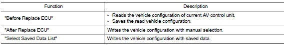
Configuration has three functions as follows:
CAUTION:
- When replacing AV control unit, you must perform “Select Saved Data List” or "After Replace ECU" with CONSULT.
- Complete the procedure of “Select Saved Data List” or "After Replace ECU" in order.
- If you set incorrect “Select Saved Data List” or "After Replace ECU", incidents might occur.
- Configuration is different for each vehicle model. Confirm configuration of each vehicle model.
- Never perform “Select Saved Data List” or "After Replace ECU" except for new AV control unit.
Configuration (av control unit) : work procedure
1.WRITING MODE SELECTION
 CONSULT
Select “Reprogramming, Configuration” of AV control unit.
When writing saved data>>GO TO 2.
When writing manually>>GO TO 3.
2.PERFORM “SAVED DATA LIST”
 CONSULT
Automatically “Operation Log Selection” window will display if “Before Replace ECU” was performed. Select applicable file from the “Save Data List” and press “Confirm”.
>> Work End.
3.PERFORM “AFTER REPLACE ECU” OR “MANUAL CONFIGURATION”
 CONSULT
- Select “After Replace ECU” or “Manual Configuration”.
- Identify the correct model and configuration list. Refer to AV-252, "CONFIGURATION (AV CONTROL UNIT) : Configuration List".
- Confirm and/or change setting value for each item.
CAUTION:
Thoroughly read and understand the vehicle specification. ECU control may not operate normally if the setting is not correct.
- Select “Next”.
CAUTION:
Make sure to select “Next”, confirm each setting value and press “OK” even if the indicated configuration of brand new AV control unit is same as the desirable configuration. If not, configuration which is set automatically by selecting vehicle model can not be memorized.
- When "Completed", select "End".
>> GO TO 4.
4.OPERATION CHECK
Confirm that each function controlled by AV control unit operates normally.
>> Work End.
Configuration (av control unit) : configuration list
CAUTION:
Thoroughly read and understand the vehicle specification. Incorrect settings may result in abnormal control of ECU.
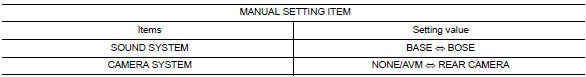
⇔: Items which confirm vehicle specifications
 Wiring diagram
Navigation without bose
Wiring diagram
...
 Dtc/circuit diagnosis
U1000 can comm circuit
DTC Logic
DTC DETECTION LOGIC
CONSULT Display
DTC Detection Condition
Possible Cause
CAN COMM CIRCUIT
[U1000]
AV control unit is not transmitting ...
Other materials:
Diagnosis description : system readiness
test (SRT) code
System Readiness Test (SRT) code is specified in Service $01 of SAE J1979/ISO
15031-5.
As part of an enhanced emissions test for Inspection & Maintenance (I/M),
certain states require the status of
SRT be used to indicate whether the ECM has completed self-diagnosis of major
emission s ...
Rear seat belt
Exploded View - Seat Belt Retractor
Seat belt retractor (RH)
Seat belt retractor (center)
Seat belt retractor (LH)
Front
Removal and Installation - Seat Belt Retractor
REMOVAL
Remove the rear parcel shelf finisher. Refer to INT-33, "Removal and
Installation".
Re ...
System
Tire pressure monitoring system
TIRE PRESSURE MONITORING SYSTEM : System Diagram
TIRE PRESSURE MONITORING SYSTEM : System Description
The BCM has pressure judgment and trouble diagnosis functions. When the
BCM detects low inflation pressure
or another unusual symptom, the low tire pr ...
