Nissan Sentra Service Manual: Basic inspection
Diagnosis and repair workflow
Work Flow
OVERALL SEQUENCE
DETAILED FLOW
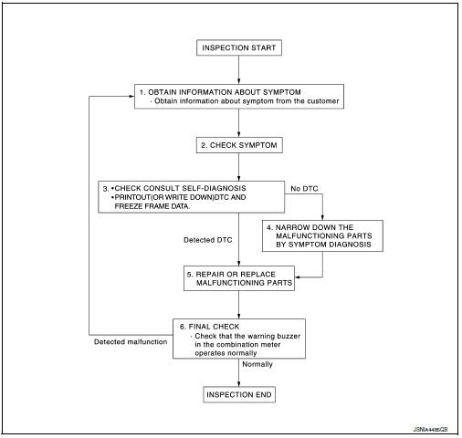
1.OBTAIN INFORMATION ABOUT SYMPTOM
Interview the customer to obtain as much information as possible about the conditions and environment under which the malfunction occurred.
>> GO TO 2.
2.CHECK SYMPTOM
- Check the symptom based on the information obtained from the customer.
- Check if any other malfunctions are present.
>> GO TO 3.
3.CHECK CONSULT SELF-DIAGNOSIS RESULTS
Connect CONSULT and perform self-diagnosis. Refer to MWI-26, "DTC Index".
Are self-diagnosis results normal? YES >> GO TO 4.
NO >> GO TO 5.
4.NARROW DOWN MALFUNCTIONING PARTS BY SYMPTOM DIAGNOSIS
Perform symptom diagnosis and narrow down the malfunctioning parts.
>> GO TO 5.
5.REPAIR OR REPLACE MALFUNCTIONING PARTS
Repair or replace malfunctioning parts.
NOTE:
If DTC is displayed, erase DTC after repairing or replacing malfunctioning parts.
>> GO TO 6.
6.FINAL CHECK
Check that the warning buzzer in the combination meter operates normally.
Does it operate normally? YES >> Inspection End.
NO >> GO TO 1.
 Wiring diagram
Warning chime system
Wiring diagram
...

Other materials:
Strg branch line circuit
Diagnosis Procedure
1.Check connector
Turn the ignition switch off
Disconnect the battery cable from the negative terminal.
Check the terminals and connectors of the steering angle sensor for
damage, bend and loose connection
(unit side and connector side).
Is the inspection result ...
Manual operation
Fan speed control
Press the fan control buttons to
manually
control the fan speed.
Press the AUTO button to return to automatic
control of the fan speed.
Air recirculation
Press the air recirculation
button to recirculate
interior air inside the vehicle. The
indicator light on the b ...
Precaution
Precaution for Supplemental Restraint System (SRS) "AIR BAG" and "SEAT
BELT PRE-TENSIONER"
The Supplemental Restraint System such as “AIR BAG” and “SEAT BELT PRE-TENSIONER”,
used along
with a front seat belt, helps to reduce the risk or severity of injur ...
