
Nissan Sentra Service Manual: Brake pedal
Inspection
BRAKE PEDAL HEIGHT
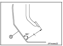
Check the brake pedal height (H1) between the dash lower panel (1) and the brake pedal upper surface.
Brake pedal height (H1) : Refer to BR-54, "Brake Pedal".
CAUTION:
Check the brake pedal height with the floor trim removed.
STOP LAMP SWITCH AND BRAKE PEDAL POSITION SWITCH
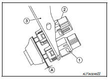
Check the clearance (A) between the switch assembly bracket (3), the stop lamp switch (2) and the brake pedal position switch (if equipped) (1).
Clearance (A) : Refer to BR-54, "Brake Pedal".
STOP LAMP SWITCH AND BRAKE PEDAL POSITION SWITCH
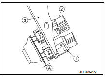
Check the clearance (A) between the switch assembly bracket (3), the stop lamp switch (2) and the brake pedal position switch (if equipped) (1).
Clearance (A) : Refer to BR-54, "Brake Pedal".
CAUTION:
The stop lamp must turn off when the brake pedal is released.
NOTE:
Pull the brake pedal pad to check that both the stop lamp switch (2) and brake pedal position switch (1) contact ends to brake pedal bracket (3) clearance (A) are within specification.
BRAKE PEDAL PLAY
Check that brake pedal play does not exist.
DEPRESSED BRAKE PEDAL HEIGHT
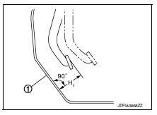
Check the brake pedal height (H2) between the dash lower panel (1) and the brake pedal upper surface when depressing the brake pedal at 490 N (50 kg, 110 lb) while turning engine ON.
Depressed brake pedal height (H2) : Refer to BR-54, "Brake Pedal".
CAUTION:
Check the depressed brake pedal height with the floor trim removed.
 Basic inspection
...
 Brake fluid
Inspection
BRAKE FLUID LEVEL
Make sure that the brake fluid level in the reservoir tank is between
the MAX and MIN lines.
Visually check around the reservoir tank for brake fluid leakage.
I ...
Other materials:
Diagnosis and repair workflow
Work Flow
OVERALL SEQUENCE
DETAILED FLOW
1. OBTAIN INFORMATION ABOUT SYMPTOM
Interview the customer to obtain as much information as possible about the
conditions and environment under
which the malfunction occurred.
>> GO TO 2.
2. CONFIRM THE SYMPTOM
Check the malfunction on the ...
Preparation
Special Service Tools
The actual shapes of Kent-Moore tools may differ from those of special
service tools illustrated here.
*: The O-ring as a unit part is set as a SST.
Commercial Service Tools
...
Continuously Variable Transmission (CVT) (if so equipped)
The ignition lock is designed so that the ignition
switch cannot be turned to the LOCK position
until the shift lever is moved to the P (Park)
position.
When moving the ignition switch to the
LOCK position, make sure the shift lever is in
the P (Park) position.
When removing the key ...
