
Nissan Sentra Service Manual: Basic inspection
Diagnosis and repair work flow
Work flow
OVERALL SEQUENCE
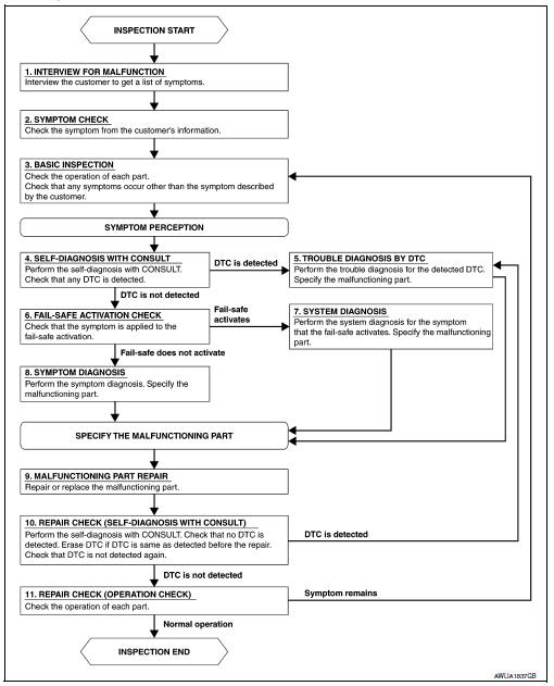
DETAILED FLOW
1.INTERVIEW FOR MALFUNCTION
Find out what the customer's concerns are.
>> GO TO 2
2.SYMPTOM CHECK
Verify the symptom from the customer's information.
>> GO TO 3
3.BASIC INSPECTION
Check the operation of each part. Check that any concerns occur other than those mentioned in the customer interview.
>> GO TO 4
4.SELF-DIAGNOSIS WITH CONSULT
Perform the self diagnosis with CONSULT. Check that any DTC is detected.
Is any DTC detected? YES >> GO TO 5
NO >> GO TO 6
5.TROUBLE DIAGNOSIS BY DTC
Perform the trouble diagnosis for the detected DTC. Specify the malfunctioning part.
>> GO TO 9
6.FAIL-SAFE ACTIVATION CHECK
Determine if the customer's concern is related to fail-safe activation.
Does the fail-safe activate? YES >> GO TO 7
NO >> GO TO 8
7.SYSTEM DIAGNOSIS
Perform the system diagnosis for the system in which the fail-safe activates. Specify the malfunctioning part.
>> GO TO 9
8.SYMPTOM DIAGNOSIS
Perform the symptom diagnosis. Specify the malfunctioning part.
>> GO TO 9
9.MALFUNCTION PART REPAIR
Repair or replace the malfunctioning part.
>> GO TO 10
10.REPAIR CHECK (SELF-DIAGNOSIS WITH CONSULT)
Perform the self diagnosis with CONSULT. Verify that no DTCs are detected. Erase all DTCs detected prior to the repair. Verify that DTC is not detected again.
Is any DTC detected? YES >> GO TO 5
NO >> GO TO 11
11.REPAIR CHECK (OPERATION CHECK)
Check the operation of each part.
Does it operate normally?
YES >> Inspection End.
NO >> GO TO 3
 Wiring diagram
Headlamp
Wiring diagram
Daytime light system
Wiring diagram
Auto light system
Wiring diagram
Front fog lamp
Wiring diagram
...

Other materials:
Using the system
The NISSAN Voice Recognition system allows
hands-free operation of the Bluetooth® Phone
System.
If the vehicle is in motion, some commands may
not be available so full attention may be given to
vehicle operation.
Initialization
When the ignition switch is placed in the ON
position, NISSAN ...
Drive belt
Exploded View
Alternator
Drive belt auto-tensioner
Crankshaft pulley
A/C compressor
Water pump
Drive belt
Possible use range
New drive belt range
Indicator
Removal and Installation
REMOVAL
Remove the front fender protector (RH) front side bolts and clips. Refer ...
P0171 Fuel injection system function
DTC Logic
DTC DETECTION LOGIC
With the Air/Fuel Mixture Ratio Self-Learning Control, the actual mixture
ratio can be brought closely to the
theoretical mixture ratio based on the mixture ratio feedback signal from the
A/F sensors 1. The ECM calculates
the necessary compensation to correct th ...
