Nissan Sentra Owners Manual: Forward-facing child restraint installation using LATCH
Refer to all Warnings and Cautions in the ŌĆ£Child safetyŌĆØ and ŌĆ£Child restraintsŌĆØ sections before installing a child restraint.
Follow these steps to install a forward-facing child restraint using the LATCH system:
- Position the child restraint on the seat. Always follow the child restraint manufacturerŌĆÖs instructions.
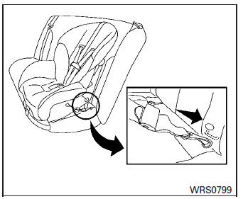
Forward-facing web-mounted ŌĆō step 2
- Secure the child restraint anchor attachments
to the LATCH lower anchors. Check
to make sure the LATCH attachment is properly
attached to the lower anchors.
If the child restraint is equipped with a top tether strap, route the top tether strap and secure the tether strap to the tether anchor point. See ŌĆ£Installing top tether strapŌĆØ in this section. Do not install child restraints that require the use of a top tether strap in seating positions that do not have a top tether anchor.
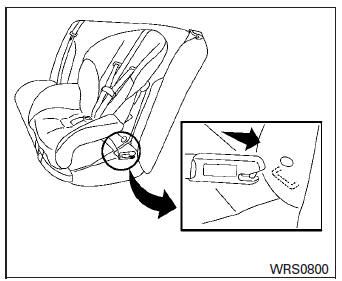
Forward-facing rigid-mounted ŌĆō step 2
- The back of the child restraint should be
secured against the vehicle seatback.
If necessary, adjust or remove the head restraint/headrest to obtain the correct child restraint fit. If the head restraint/headrest is removed, store it in a secure place. Be sure to reinstall the head restraint/headrest when the child restraint is removed.
See ŌĆ£Head restraints/headrestsŌĆØ in this section for head restraint/headrest adjustment information.
If the seating position does not have an adjustable head restraint/headrest and it is interfering with the proper child restraint fit, try another seating position or a different child restraint.

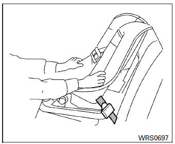
Forward-facing ŌĆō step 4
- For child restraints that are equipped with
webbing-mounted attachments, remove any
additional slack from the anchor attachments.
Press downward and rearward firmly in the center of the child restraint with your knee to compress the vehicle seat cushion and seatback while tightening the webbing of the anchor attachments.
- Tighten the tether strap according to the manufacturerŌĆÖs instructions to remove any slack.
Forward-facing ŌĆō step 6
- After attaching the child restraint, test it before you place the child in it. Push it from side to side while holding the child restraint near the LATCH attachment path. The child restraint should not move more than 1 inch (25 mm), from side to side. Try to tug it forward and check to see if the LATCH attachment holds the restraint in place. If the restraint is not secure, tighten the LATCH attachment as necessary, or put the restraint in another seat and test it again. You may need to try a different child restraint. Not all child restraints fit in all types of vehicles.
- Check to make sure the child restraint is properly secured prior to each use. If the child restraint is loose, repeat steps 1 through 6.
 Rear-facing child restraint installation using the seat belts
WARNINGThe three-point seat belt with Automatic
Locking Retractor (ALR) must be used
when installing a child restraint. Failure to
use the ALR mode will result in the child
rest ...
 Forward-facing child restraint installation using the seat belts
WARNINGThe three-point seat belt with Automatic
Locking Retractor (ALR) must be used
when installing a child restraint. Failure to
use the ALR mode will result in the child
restrain ...
Other materials:
B0021 Side curtain air bag module LH
Description
DTC B0021 LH SIDE CURTAIN AIR BAG MODULE
The LH side curtain air bag module is wired to the air bag diagnosis sensor
unit. The air bag diagnosis sensor
unit will monitor for opens and shorts in detected lines to the LH side curtain
air bag module.
PART LOCATION
Refer to SRC-5, ...
Removal and installation
BCM
Removal and installation
Note:
Before replacing BCM, perform ą▓ąéčÜREAD CONFIGURATIONą▓ąéč£ to save or print
current vehicle specification. Refer
to BCS-61, "CONFIGURATION (BCM) : Description".
Removal
Disconnect the negative battery terminal. Refer to pg-52, "removal a ...
Manual control
While using the Voice Recognition system, it is
possible to select menu options by using the
steering wheel controls instead of speaking voice
commands. The manual control mode does not
allow dialing a phone number by digits. The user
may select an entry from the Phonebook or Recent
Calls list ...
