Nissan Sentra Service Manual: Removal and installation
EXHAUST SYSTEM
Exploded View
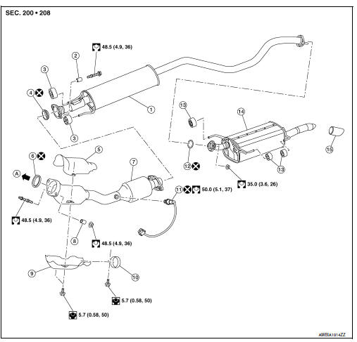
- Sub muffler
- Spring
- Mounting rubber
- Seal bearing
- Catalyst shroud (upper)
- Seal bearing
- Exhaust front tube
- Spring
- Catalyst shroud (lower)
- Clamp
- Heated oxygen sensor 2
- Ring gasket
- Mounting rubber
- Main muffler
- Exhaust finisher (if equipped)
- To exhaust manifold
Removal and Installation
REMOVAL
- Disconnect each joint and mounting rubber.
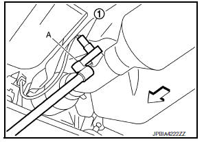
- Remove heated oxygen sensor 2 (1) using Tool (A).
Tool number : KV10114400 (J-38365)
CAUTION:
- Discard any heated oxygen sensor which has been dropped from a height of more than 0.5 m (19.7 in) onto a hard surface such as a concrete floor; use a new one.
- Before installing new heated oxygen sensor, clean exhaust system threads using oxygen sensor thread cleaner and approved anti-seize lubricant.
Oxygen sensor thread cleaner : J-43897-12
Oxygen sensor thread cleaner : J-43897-18
INSTALLATION
Installation is in the reverse order of removal.
CAUTION:
- Always replace seal bearings with new ones when reassembling.
- Discard any heated oxygen sensor 2 which has been dropped onto a hard surface such as a concrete floor. Use a new one.
- Before installing a new heated oxygen sensor 2, clean exhaust system threads using the oxygen sensor thread cleaner and apply anti-seize lubricant.
- Do not over tighten heated oxygen sensor 2. Doing so may cause damage to the heated oxygen sensor 2, resulting in the “MIL” coming on.
- Prevent rust preventives from adhering to the sensor body.
- If heat insulator is badly deformed, repair or replace it. If deposits such as mud pile up on the heat insulator, remove them.
- When installing heat insulator avoid large gaps or interference between heat insulator and each exhaust pipe.
- Remove deposits from the sealing surface of each connection. Connect them securely to avoid gas fume leaks.
- When installing each mounting rubber, use silicon oil to avoid twisting.
- Temporarily tighten nuts and bolts. Check each part for unusual interference and mounting rubber interference, and then tighten them to the specified torque.
- When installing each mounting rubber, avoid twisting or unusual extension in up/down, front/rear and right/left directions.
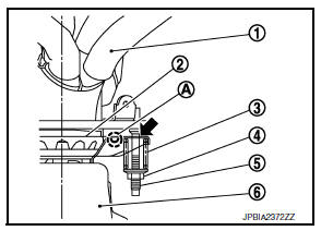
Exhaust Manifold to Exhaust Front Tube
- Securely insert seal bearing (2) into exhaust manifold (1) in the direction shown.
- Spring
- Nut
- Stud bolt
- Exhaust front tube
CAUTION:
Be careful not to damage seal bearing surface when installing.
- Install spring and tighten nut.
CAUTION:
- Fasten stud bolts to the flange of exhaust manifold side to the specified torque before installing nuts.
- Ensure springs are seated correctly on the flange and not sitting on protrusion (A).
- Be careful that stud bolt does not interfere with mounting hole of
exhaust front tube (
 ).
).
- After installing, check that stud bolt does not interfere with mounting hole of exhaust front tube.
Exhaust Front Tube to Center Muffler
- Securely insert seal bearing (2) into exhaust front tube (1) in the direction shown.
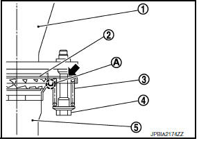
- Spring
- Bolt
- Center muffler
CAUTION:
Be careful not to damage seal bearing surface when installing.
- Install spring and tighten bolt.
CAUTION:
- Ensure springs are seated correctly on the flange and not sitting on protrusion (A).
- Be careful that bolt does not interfere with mounting hole of
center muffler (
 ).
).
- After installing, check that bolt does not interfere with mounting hole of center muffler.
Inspection
INSPECTION AFTER INSTALLATION
- Check clearance between tail tube and rear bumper is even.
- With engine running, check exhaust tube joints for gas fume leaks and unusual noises.
- Check to ensure that mounting brackets and mounting rubbers are installed properly and free from undue stress. Improper installation could result in excessive noise and vibration.
 Periodic maintenance
EXHAUST SYSTEM
Inspection
Check exhaust pipes, muffler, and mounting for improper attachment,
leakage, cracks, damage or deterioration.
If anything is found, repair or replace damaged parts.
...
 Starting system
...
Other materials:
Phone settings
To access the phone settings:
Press the [ ] button.
Touch the “Settings” key.
Touch the “Phone & Bluetooth” key.
Touch the “Phone Settings” key and adjust
the following settings as desired:
Sort Phonebook By:
Touch “First Name” or “Last Name” to
choose ...
Diagnosis system (bcm)
Common item
COMMON ITEM : CONSULT Function (BCM - COMMON ITEM)
Application item
Consult performs the following functions via can communication with bcm.
Direct diagnostic mode
Description
Ecu identification
The bcm part number is displayed.
Self diagnostic result
...
P1550 Battery current sensor
DTC Logic
DTC DETECTION LOGIC
DTC No.
CONSULT screen terms
(Trouble diagnosis content)
DTC detecting condition
Possible cause
P1550
BAT CURRENT SENSOR
(Battery current sensor)
The output voltage of the battery current
sensor remains within the specified
r ...
