Nissan Sentra Service Manual: Removal and installation
Generator
Exploded view
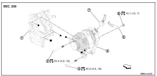
- Thermostat housing
- Generator bolt (upper)
- Generator bolt (lower)
- Generator
- B” terminal harness
- “B” terminal nut
- Generator harness connector
 Front
Front
Removal and installation
Note:
When removing components such as hoses,tubes\lines,etc,cap or plug openings to prevent fluid from spilling.
Removal
- Disconnect the battery negative terminal. Refer to PG-50, "Removal and Installation (Battery)".
- Remove cooling fan. Refer to CO-17, "Removal and Installation".
- Remove drive belt. Refer to em-15, "removal and installation".
- Disconnect generator harness connector.
- Remove “B” terminal nut, and then disconnect “B” terminal harness.
- Remove generator bolt (upper).
- Completely loosen generator bolt (lower) (1), and pull it out until the bolt head is in contact with the side member. And then, remove the generator (2) by pulling it forward.
 : Front
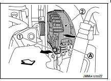
Note:
The generator can be removed together with the bolts by pulling it forward and using the thermostat housing bolt hole cutout (a).
- Remove generator upward from the vehicle.
Installation
- Installation is in the reverse order of removal.
- Refill engine coolant. Refer to co-12, "changing engine coolant".
Caution:
- Temporarily tighten the generator bolts in order from the lower to the upper, and then tighten them in order from the upper to the lower.
- For the generator, the front side (pulley side) surface is the reference surface. Fit the reference surface to the generator mounting part, and then tighten the bolts.
- Be careful to tighten “b” terminal nut carefully.
- For this model, the power generation voltage variable control system that controls the power generation voltage of the generator has been adopted. Therefore, the power generation voltage variable control system operation inspection should be performed after replacing the generator, and then make sure that the system operates normally. Refer to chg-8, "system description".
Inspection
Generator pulley inspection
Perform the following.
- Make sure that generator pulley does not rattle.
- Make sure that generator pulley nut is tight.
Note:
Replace generator as an assembly if necessary.
 Symptom diagnosis
Charging system
Symptom table
...
 Service data and specifications (SDS)
Generator
*: Always check with the parts department for the latest parts information. ...
Other materials:
P2859 Clutch A Pressure
DTC Logic
DTC DETECTION LOGIC
DTC
CONSULT screen terms
(Trouble diagnosis content)
DTC detection condition
Possible causes
P2859
CLUTCH A PRESSURE
(Clutch A Pressure Disengagement
Performance)
The detection conditions continuously for 200
msec or more un ...
Diagnosis and repair workflow
Work Flow
OVERALL SEQUENCE
*1: Include 1st trip DTC.
*2: Include 1st trip freeze frame data.
DETAILED FLOW
1.GET INFORMATION FOR SYMPTOM
Get the detailed information from the customer about the symptom (the
condition and the environment when
the incident/malfunction occurred) using the ...
Precaution for Work
When removing or disassembling each component, be careful not to damage
or deform it. If a component
may be subject to interference, be sure to protect it with a shop cloth.
When removing (disengaging) components with a screwdriver or similar
tool, be sure to wrap the component
with a ...
