
Nissan Sentra Service Manual: Removal and installation
Horn
Exploded view
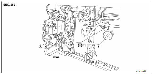
- Horn high
- Horn low
 Front
Front
Note:
Shown with the front fascia removed for clarity.
Removal and installation
Horn low
Removal
- Remove the core support cover. Refer to ext-23, "removal and installation".
- Disconnect the horn low harness connectors.
Note:
The harness connector locations prior to removal.
- Remove the horn nut and the horn low.
Installation
Installation is in the reverse order of removal.
Note:
Install the harness connector in the proper locations.
Horn high
Removal
- Partially remove the rh fender protector. Refer to ext-28, "fender protector : removal and installation - front fender protector".
- Disconnect the horn high harness connectors.
Note:
The harness connector locations prior to removal.
- Remove the horn nut and the horn high.
Installation
Installation is in the reverse order of removal.
Note:
Install the harness connector in the proper locations.
 Wiring diagram
Horn
Wiring diagram
...

Other materials:
P0850 PNP Switch
Description
For CVT models, transmission range switch is turn ON when the selector lever
is P or N.
For M/T models, park/neutral position (PNP) range switch is ON when the selector
lever is Neutral position.
ECM detects the position because the continuity of the line (the ON) exists.
DTC ...
Trunk room lamp
Removal and Installation
Warning:
Do not touch bulb while it is lit or right after being turned off.
Burning may result.
Caution:
Do not touch glass surface of the bulb with bare hands or allow oil or
grease to get on it to prevent
damage to bulb.
Release the tab (b) to open the lens.
...
Precaution
Precaution for supplemental restraint system (srs) "air bag" and "seat
belt pre-tensioner"
The supplemental restraint system such as “air bag” and “seat belt pre-tensioner”,
used along
with a front seat belt, helps to reduce the risk or severity of injur ...
