Nissan Sentra Service Manual: Power supply and ground circuit
Diagnosis procedure
Regarding wiring diagram information, refer to bcs-51, "wiring diagram".
1.Check fuses and fusible link
Check that the following fuses and fusible link are not blown.
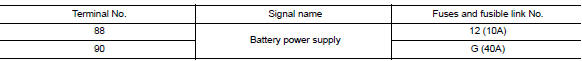
Is the fuse blown? YES >> Replace the blown fuse or fusible link after repairing the affected circuit.
NO >> GO TO 2.
2.Check power supply circuit
- Disconnect bcm connector m85.
- Check voltage between bcm connector m85 and ground.
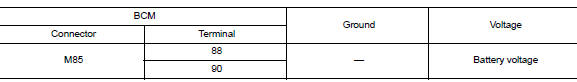
Is the inspection result normal? YES >> GO TO 3.
NO >> Repair harness or connector.
3.Check ground circuit
Check continuity between bcm connector m85 and ground.
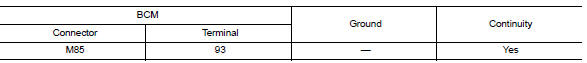
Is the inspection result normal? YES >> Inspection End.
NO >> Repair harness or connector.
Combination meter buzzer
Component function check
1.Check function
- Select intelligent key of bcm using consult.
- Select inside buzzer in active test mode.
- Touch Key, Knob or Take Out to check that it works normally.
Is the inspection result normal? Yes >> Combination meter buzzer is OK.
No >> Refer to DLK-91, "Diagnosis Procedure".
Diagnosis Procedure
1.CHECK METER BUZZER CIRCUIT
Refer to WCS-28, "Component Function Check".
Is the inspection result normal? Yes >> GO TO 2.
No >> Repair or replace harness.
2.CHECK INTERMITTENT INCIDENT
Refer to GI-39, "Intermittent Incident".
>> Inspection End.
 DTC/circuit diagnosis
U1000 CAN COMM CIRCUIT
Description
Refer to lan-7, "can communication system : system description".
Dtc logic
Dtc detection logic
Note:
U1000 can be set if a module harness was disconn ...
 Door lock actuator
Driver side
Driver side : component function check
1.CHECK FUNCTION
Select DOOR LOCK of BCM using CONSULT.
Select DOOR LOCK in ACTIVE TEST mode.
Touch ALL LOCK or ALL UNLK to check that it w ...
Other materials:
Starting the engine
Apply the parking brake.
CVT model:
Move the shift lever to P (Park) or N (Neutral).
P (Park) is recommended.
The shift lever cannot be moved out of
P (Park) and into any of the other gear
positions if the ignition switch is
turned to the OFF position or if the key
is removed from th ...
Front disc brake
Exploded View
Cap
Bleeder valve
Cylinder body
Piston seal
Piston
Piston boot
Upper sliding pin
Lower sliding pin
Sliding pin boot
Bushing
Torque member
Apply brake fluid
Apply rubber grease
Disassembly and Assembly
DISASSEMBLY
Place a wooden block as shown, and ...
P0746 Pressure control solenoid A
DTC Logic
DTC DETECTION LOGIC
DTC
CONSULT screen terms
(Trouble diagnosis content)
DTC detection condition
Possible causes
P0746
PRESSURE CONTROL SOLENOID
A
(Pressure Control Solenoid A
Performance/Stuck Off)
The detecting condition A or detection conditi ...
