Nissan Sentra Service Manual: P2765 Input speed sensor B
DTC Logic
DTC DETECTION LOGIC
| DTC | CONSULT screen terms (Trouble diagnosis content) | DTC detection condition | Possible causes |
| P2765 | INPUT SPEED SENSOR B (Input/Turbine Speed Sensor B Circuit) | The secondary speed sensor value is less
than 150 rpm continuously for 5 seconds or
more under the following diagnosis conditions: Diagnosis conditions
|
|
| The secondary pulley speed sensor value is
240 rpm or less continuously for 500 msec or
more under the following diagnosis conditions: Diagnosis condition
|
DTC CONFIRMATION PROCEDURE
CAUTION:
Be careful of the driving speed.
1.PREPARATION BEFORE WORK
If another “DTC CONFIRMATION PROCEDURE” occurs just before, turn ignition switch OFF and wait for at least 10 seconds, then perform the next test.
>> GO TO 2.
2.CHECK DTC DETECTION
- Start the engine
- Drive the vehicle
- Maintain the following conditions for 10 seconds or more.
Selector lever : “D” position
Vehicle speed : 55 km/h (34 MPH) or more
- Stop the vehicle.
- Check the first trip DTC.
Is “P2765” detected? YES >> Go to TM-223, "Diagnosis Procedure".
NO >> INSPECTION END
Diagnosis Procedure
1.CHECK SECONDARY SPEED SENSOR POWER CIRCUIT
- Turn ignition switch OFF.
- Disconnect secondary speed sensor connector.
- Turn ignition switch ON.
- Check voltage between secondary speed sensor harness connector terminal and ground.
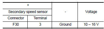
Is the inspection result normal? YES >> GO TO 2.
NO >> GO TO 6.
2.CHECK SECONDARY SPEED SENSOR GROUND CIRCUIT
Check continuity between of secondary speed sensor harness connector terminal and ground.
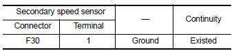
Is the inspection result normal? YES >> GO TO 3.
NO >> Repair or replace malfunctioning parts.
3.CHECK CIRCUIT BETWEEN SECONDARY SPEED SENSOR AND TCM (PART 1)
- Turn ignition switch OFF.
- Disconnect TCM connector.
- Check continuity between secondary speed sensor harness connector terminal and TCM harness connector terminal.
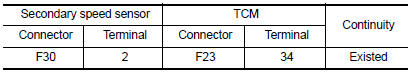
Is the inspection result normal? YES >> GO TO 4.
NO >> Repair or replace malfunctioning parts.
4.CHECK CIRCUIT BETWEEN SECONDARY SPEED SENSOR AND TCM (PART 2)
Check continuity between secondary speed sensor harness connector terminal and ground.
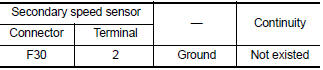
Is the inspection result normal? YES >> GO TO 5.
NO >> Repair or replace malfunctioning parts.
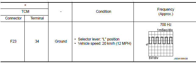
5.Check TCM Input signals
- Connect all of disconnected connectors.
- Lift the vehicle.
- Start the engine.
- Check frequency of secondary speed sensor.
Is the inspection result normal? YES >> Check intermittent incident. Refer to GI-39, "Intermittent Incident".
NO >> Replace secondary speed sensor. TM-269, "Removal and Installation".
6.DETECT MALFUNCTIONING ITEMS
Check the following items:
- Harness open circuit or short circuit between ignition switch and IPDM E/R. Refer to PG-20, "Wiring Diagram — Ignition Power Supply —".
- Harness open circuit or short circuit between IPDM E/R and secondary speed sensor.
- 10A fuse (No.45, IPDM E/R). Refer to PG-49, "IPDM E/R Terminal Arrangement".
- IPDM E/R
Is the check result normal? YES >> Check intermittent incident. Refer to GI-39, "Intermittent Incident".
NO >> Repair or replace malfunctioning parts.
 P1588 G Sensor
DTC Logic
DTC DETECTION LOGIC
DTC
CONSULT screen terms
(Trouble diagnosis content)
DTC detection condition
Possible causes
P1588
G Sensor
(Gravity S ...
 P2857 Clutch A Pressure
DTC Logic
DTC DETECTION LOGIC
DTC
CONSULT screen terms
(Trouble diagnosis content)
DTC detection condition
Possible causes
P2857
CLUTCH A PRESSURE
(Clutch A Pressu ...
Other materials:
Rear window defogger power supply and ground circuit
Description
Heats the heating wire with the power supply from the rear window defogger
relay to prevent the rear window
from fogging up.
Component function check
1. Check rear window defogger
Check that the heating wire of rear window defogger is heated when turning
the rear window defogge ...
Brake pedal position switch
Component Function Check
1.CHECK BRAKE PEDAL POSITION SWITCH FUNCTION
With CONSULT
Turn ignition switch ON.
Select “ENGINE” using CONSULT.
Select “BRAKE SW1” in “DATA MONITOR” mode.
Check “BRAKE SW1” indication under the following conditions.
...
Easy fill tire alert does not activate
Description
The Easy Fill Tire Alert does not function while inflating a tire when the
select lever position is in P-range with
the ignition switch ON. Refer to WT-8, "TIRE PRESSURE MONITORING SYSTEM : Easy
Fill Tire Alert Function".
Diagnosis Procedure
1. LOCATION CHANGE
Move the ...
