Nissan Sentra Service Manual: EPS branch line circuit
Diagnosis procedure
1.Check connector
- Turn the ignition switch off.
- Disconnect the battery cable from the negative terminal.
- Check the terminals and connectors of the EPS control unit for damage, bend and loose connection (unit side and connector side).
Is the inspection result normal? Yes >> go to 2.
No >> repair the terminal and connector.
2.Check harness for open circuit
- Disconnect the connector of EPS control unit.
- Check the resistance between the eps control unit harness connector terminals.
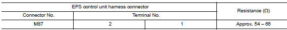
Is the measurement value within the specification? YES >> GO TO 3.
NO >> Repair the EPS control unit branch line.
3.Check power supply and ground circuit
Check the power supply and the ground circuit of the eps control unit. Refer to stc-22, "diagnosis procedure".
Is the inspection result normal? Yes (present error)>>replace the eps control unit. Refer to stc-39, "removal and installation".
Yes (past error)>>error was detected in the eps control unit branch line.
No >> repair the power supply and the ground circuit
 Dlc branch line circuit
Diagnosis procedure
1.Check connector
Turn the ignition switch off.
Disconnect the battery cable from the negative terminal
Check the terminals and connectors of the data link connector for d ...
 M&A branch line circuit
Diagnosis procedure
1.Check connector
Turn the ignition switch off.
Disconnect the battery cable from the negative terminal.
Check the terminals and connectors of the combination meter for da ...
Other materials:
P0137 HO2S2
DTC Logic
DTC DETECTION LOGIC
The heated oxygen sensor 2 has a much longer switching time
between rich and lean than the air fuel ratio (A/F) sensor 1. The oxygen
storage capacity of the three way catalyst (manifold) causes the
longer switching time. To judge the malfunctions of heated oxygen
...
Anti-lock Braking System (ABS)
WARNING
The Anti-lock Braking System (ABS) is a
sophisticated device, but it cannot prevent
accidents resulting from careless
or dangerous driving techniques. It can
help maintain vehicle control during
braking on slippery surfaces. Remember
that stopping distances ...
Head restraints/Headrests
WARNINGHead restraints/headrests supplement
the other vehicle safety systems. They may
provide additional protection against injury
in certain rear end collisions. Adjustable
head restraints/headrests must be
adjusted properly, as specified in this section.
Check the adjus ...
