Nissan Sentra Service Manual: Electric ignition system
ELECTRIC IGNITION SYSTEM : System Description
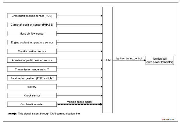
SYSTEM DIAGRAM
*1: CVT models
*2: M/T models
Input/output signal chart
| Sensor | Input Signal to ECM | ECM function | Actuator | |
| Crankshaft position sensor (POS) |
|
Ignition timing control | Ignition coil (with power transistor) | |
| Camshaft position sensor (PHASE) | ||||
| Mass air flow sensor | Amount of intake air | |||
| Engine coolant temperature sensor | Engine coolant temperature | |||
| Throttle position sensor | Throttle position | |||
| Accelerator pedal position sensor | Accelerator pedal position | |||
| Transmission range switch*1 | Gear position | |||
| Park/neutral position (PNP) switch*2 | ||||
| Battery | Battery voltage*3 | |||
| Knock sensor | Engine knocking condition | |||
| Combination meter | CAN communication | Vehicle speed signal | ||
*1: CVT models
*2: M/T models
*3: ECM determines the start signal status by the signals of engine speed and battery voltage.
SYSTEM DESCRIPTION
Firing order: 1 - 3 - 4 - 2
The ignition timing is controlled by the ECM to maintain the best air-fuel ratio for every running condition of the engine. The ignition timing data is stored in the ECM.
The ECM receives information such as the injection pulse width and camshaft position sensor (PHASE) signal.
Computing this information, ignition signals are transmitted to the power transistor.
During the following conditions, the ignition timing is revised by the ECM according to the other data stored in the ECM.
- At starting
- During warm-up
- At idle
- At low battery voltage
- During acceleration
The knock sensor retard system is designed only for emergencies. The basic ignition timing is programmed within the anti-knocking zone, if recommended fuel is used under dry conditions. The retard system does not operate under normal driving conditions. If engine knocking occurs, the knock sensor monitors the condition.
The signal is transmitted to the ECM. The ECM retards the ignition timing to eliminate the knocking condition.
 Multiport fuel injection system
MULTIPORT FUEL INJECTION SYSTEM : System
Description
SYSTEM DIAGRAM
*1: ECM determines the start signal status by the signals of engine speed and
battery voltage.
*2: M/T models
*3: CVT mod ...
 Intake valve timing control
INTAKE VALVE TIMING CONTROL : System Description
SYSTEM DIAGRAM
INPUT/OUTPUT SIGNAL CHART
Sensor
Input signal to ECM
ECM function
Actuator
Crankshaft position sensor (P ...
Other materials:
Engine compartment check locations
MRA8DE engine
Engine oil filler cap
Brake and clutch (if so equipped) fluid
reservoir
Air cleaner
Battery
Fuse/fusible link box
Engine coolant reservoir
Radiator cap
Engine oil dipstick
Drive belt location
Windshield-washer fluid reservoir
...
Rear disc brake
Brake Burnishing
CAUTION:
Burnish contact surfaces between brake pads and disc rotor
according to the following procedure
after refinishing the disc rotor, replacing brake pads or if a soft pedal
occurs at very low mileage.
Be careful of vehicle speed. Brakes do not operate firmly/sec ...
Preparation
Special Service Tools
The actual shape of the tools may differ from those illustrated here.
Commercial Service Tools
...
