Nissan Sentra Service Manual: Door lock
Front door lock
Front door lock : exploded view
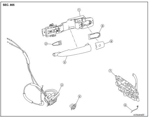
- Outside handle bracket
- Front gasket
- Outside handle
- Door lock assembly
- Door striker
- Door key cylinder rod
- Inside handle assembly
- Outside handle escutcheon
- Rear gasket
Front door lock : removal and installation
CAUTION:
Before servicing, turn ignition switch OFF, disconnect both battery terminals and wait at least three minutes.
REMOVAL
- Remove the front door outside handle. Refer to DLK-173, "FRONT DOOR HANDLE : Removal and Installation - Outside Handle".
- Remove the rear glass run.
- Disconnect the harness connector from the front door lock actuator.
- Remove screws, and the door lock assembly.
INSTALLATION
Installation is in the reverse order of removal.
Tighten front door lock screws to specified torque.
Front door lock screws: 5.8 NВ·m (0.59 kg-m, 51 in-lb)
CAUTION:
- Do not reuse front door lock assembly screws. Always replace screws with new ones when removed.
- Check front door lock cables are properly engaged to inside handle and outside handle bracket.
- When installing door key cylinder rod on the LH front door, be sure to rotate door key cylinder rod holder until a click is felt.
- After installation, check front door open/close, lock/unlock operation.
- Check front door lock assembly for poor lubrication. If necessary apply a suitable multi-purpose grease.
Rear door lock
REAR DOOR LOCK : Exploded View
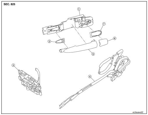
- Outside handle bracket
- Front gasket
- Inside handle assembly
- Door lock assembly
- Outside handle
- Outside handle escutcheon
- Rear gasket
REAR DOOR LOCK : Removal and Installation
REMOVAL
- Remove the rear door outside handle. Refer to DLK-176, "REAR DOOR HANDLE : Removal and Installation - Outside Handle".
- Disconnect the harness connector from the rear door lock actuator.
- Remove the screws, and the door lock assembly
INSTALLATION
Installation is in the reverse order of removal.
Tighten rear door lock screws to specified torque.
Rear door lock screws: 5.8 NВ·m (0.59 kg-m, 51 in-lb)
CAUTION:
- Do not reuse rear door lock assembly screws. Always replace screws with new ones when removed.
- Check rear door lock cables are properly engaged to inside handle and outside handle bracket.
- After installation, check rear door open/close, lock/unlock operation.
- Check rear door lock assembly for poor lubrication. If necessary apply a suitable multi-purpose grease.
 Door handle
Front door handle
Front door handle : exploded view
Outside handle bracket
Rear gasket
Front gasket
Outside handle escutcheon
Outside handle
Door key cylinder rod
Inside handle as ...
 Trunk lid
Trunk lid assembly
Trunk lid assembly : exploded view
Trunk lid hinge LH/RH
Torsion bar LH/RH
Torsion bar clips
Trunk lid finisher (if equipped)
Emergency release handle
Emergency rel ...
Other materials:
Diagnosis description : system readiness
test (SRT) code
System Readiness Test (SRT) code is specified in Service $01 of SAE J1979/ISO
15031-5.
As part of an enhanced emissions test for Inspection & Maintenance (I/M),
certain states require the status of
SRT be used to indicate whether the ECM has completed self-diagnosis of major
emission s ...
Preparation
Special Service Tool
The actual shape of the tools may differ from those illustrated here.
Commercial Service Tool
Clip list
Descriptions for clips
Replace any clips which are damaged during removal or installation.
...
Precaution
Precaution for Supplemental Restraint System (SRS) "AIR BAG" and "SEAT BELT
PRE-TENSIONER"
The supplemental restraint system such as “air bag” and “seat belt pre-tensioner”,
used along
with a front seat belt, helps to reduce the risk or severity of injur ...
