
Nissan Sentra Service Manual: Component parts
Nissan Sentra Service Manual / Driver controls / Exterior lighting system / System description / Component parts
Component Parts Location
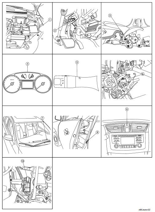
- IPDM E/R, (Headlamp high relay, Headlamp low relay, Taillamp relay and Front fog lamp relay (if equipped))
- Stop lamp switch
- Parking brake switch
- Combination meter
- Combination switch (lighting and turn signal switch)
- BCM (view with combination meter removed)
- Optical sensor
- Front door switch LH (Other doors similar)
- Hazard switch
- Daytime light relay (if equipped)
Component Description
| Part | Description |
| BCM | Controls the exterior lighting system. |
| Combination switch (Lighting & turn signal switch) | Refer to BCS-9, "COMBINATION SWITCH READING SYSTEM : System Description" (with Intelligent Key system) or BCS-80, "COMBINATION SWITCH READING SYSTEM : System Description" (without Intelligent Key system). |
| IPDM E/R | Controls the integrated relays and supplies voltage to the load according to the request from the BCM via CAN communication. |
| Stop lamp switch | Transmits power when the brake pedal is pressed to operate stop lamps. |
| Combination meter | Refer to MWI-8, "METER SYSTEM : System Description". |
| Daytime light relay (if equipped) | Sends power to the daytime lamp when operated by the IPDM E/R. |
| Front door switch LH/RH | Transmits the door open signal to the BCM. |
| Rear door switch LH/RH | |
| Optical sensor | Optical sensor converts the outside brightness (lux) to voltage and transmits the optical sensor signal to BCM to operate the autolight system. |
| Parking brake switch | Transmits the parking brake switch signal to the combination meter to operate the autolight system. |
| Hazard switch | Inputs the hazard switch signal to BCM. |

 System
Headlamp system
HEADLAMP SYSTEM : System Diagram
HEADLAMP SYSTEM : System Description
LOW BEAM OPERATION
When the lighting switch is in 2nd position, the BCM receives input
requesting the h ...
Other materials:
Basic inspection
Diagnosis and repair workflow
Work flow
OVERALL SEQUENCE
DETAILED FLOW
1.GET INFORMATION FOR SYMPTOM
Get detailed information from the customer about the symptom (the condition
and the environment when the
incident/malfunction occurred).
>> GO TO 2
2.CONFIRM THE SYMPTOM
Try to ...
Wiring diagram
Sport mode system
Wiring diagram
...
Liquid Gasket
REMOVAL OF LIQUID GASKET SEALING
After removing the bolts and nuts, separate the mating surface and
remove the liquid gasket using Tool (A).
Tool Number : KV10111100 (J-37228)
CAUTION:
Be careful not to damage the mating surfaces.
In areas where the cutter is difficult to use, use ...
В© 2014-2026 Copyright b17.nisentra.com
