Nissan Sentra Service Manual: C1164, C1165, C1166, C1167 CV/SV System
DTC Logic
Dtc detection logic
| DTC | Display Item | Malfunction detected condition | Possible causes |
| C1164 | CV 1 | When a malfunction is detected in cut valve 1. |
|
| C1165 | CV 2 | When a malfunction is detected in cut valve 2. | |
| C1166 | SV 1 | When a malfunction is detected in suction valve 1. | |
| C1167 | SV 2 | When a malfunction is detected in suction valve 2. |
DTC CONFIRMATION PROCEDURE
1.CHECK SELF DIAGNOSTIC RESULT
 With CONSULT.
-
Turn ignition switch OFF to ON.
-
Perform self diagnostic result.
Is DTC C1164, C1165, C1166 or C1167 detected? YES >> Proceed to diagnosis procedure. Refer to BRC-85, "Diagnosis Procedure".
NO >> Inspection End.
Diagnosis Procedure
Regarding Wiring Diagram information, refer to BRC-44, "Wiring Diagram".
1.CONNECTOR INSPECTION
-
Turn ignition switch OFF.
-
Disconnect ABS actuator and electric unit (control unit) connector.
-
Check connector and terminals for deformation, disconnection, looseness or damage.
Is the inspection result normal? YES >> GO TO 2.
NO >> Repair or replace as necessary.
2.Check abs actuator and electric unit (control unit) battery power supply
Check voltage between ABS actuator and electric unit (control unit) connector E33 terminal 25 and ground.
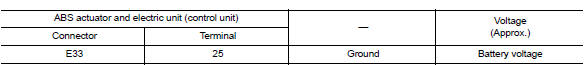
Is the inspection result normal? Yes >> go to 3.
No >> repair or replace malfunctioning components.
3.Check abs actuator and electric unit (control unit) ground circuit
Check continuity between abs actuator and electric unit (control unit) connector e33 terminals 13, 38 and ground.
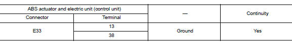
Is the inspection result normal? Yes >> replace abs actuator and electric unit (control unit). Refer to brc-110, "removal and installation".
No >> repair or replace malfunctioning components.
 C1155 BR Fluid level low
DTC Logic
Dtc detection logic
Dtc
Display item
Malfunction detected condition
Possible cause
C1155
C1155 br fluid level low
Brake fluid level is low or communication l ...
 U1000 CAN Comm circuit
DTC Logic
DTC DETECTION LOGIC
DTC
Display Item
Malfunction detected condition
Possible causes
U1000
CAN COMM CIRCUIT
When CAN communication signal is not continuously
...
Other materials:
Diagnosis system (bcm) (without intelligent
key system)
Common item
Common item : consult function (bcm -
common item)
APPLICATION ITEM
CONSULT performs the following functions via CAN communication with BCM.
Direct Diagnostic Mode
Description
ECU identification
The BCM part number is displayed.
Self Diagnostic Result
...
Wiring diagram
Rear window defogger system
Wiring diagram
...
Precautions on seat belt usage
If you are wearing your seat belt properly adjusted
and you are sitting upright and well back in
your seat with both feet on the floor, your chances
of being injured or killed in an accident and/or the
severity of injury may be greatly reduced.
NISSAN strongly encourages you and all of yo ...
