Nissan Sentra Service Manual: Abs actuator and electric unit (control unit)
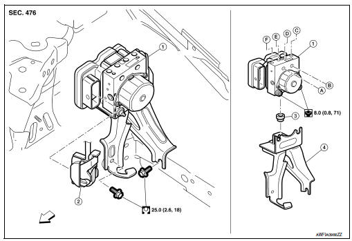
Exploded View
-
ABS actuator and electric unit (control unit)
-
ABS actuator and electric unit (control unit) harness connector
-
Bushing
-
Bracket
-
To master cylinder secondary side
-
To master cylinder primary side
-
To rear LH caliper
-
To front RH caliper
-
To front LH caliper
-
To rear RH caliper
 Front
Front
Removal and Installation
REMOVAL
-
Disconnect battery negative terminal. Refer to PG-50, "Exploded View".
-
Drain brake fluid. Refer to BR-17, "Drain and Refill".
-
Remove the cowl top. Refer to EXT-26, "Removal and Installation".
-
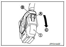
Disconnect ABS actuator and electric unit (control unit) harness connector (1), follow the procedure described below.
-
Push the pawl (A).
-
Move the lever (B) in the direction (C) until locked.
-
Disconnect ABS actuator and electric unit (control unit) harness connector.
-
Loosen flare nut of brake tube using a flare nut wrench, and then remove brake tube from ABS actuator and electric unit (control unit). Refer to BR-25, "FRONT : Exploded View".
-
Remove ABS actuator and electric unit (control unit) and bracket.
-
Remove bracket and bushing from ABS actuator and electric unit (control unit).
INSTALLATION
Installation is in the reverse order of removal.
-
When replacing with a new ABS actuator and electric unit (control unit), do not remove the protector of the brake tube mounting hole until right before the brake tube is installed.
-
When installing brake tube, tighten to the specified torque using a flare nut torque wrench so that flare nut and brake tube are not damaged. Refer to BR-25, "FRONT : Exploded View".
-
Do not remove and install ABS actuator and electric unit (control unit) by holding actuator harness.
-
Bleed air from brake piping after installation. Refer to BR-17, "Bleeding Brake System".
-
Do not apply excessive impact to actuator, such as by dropping it.
-
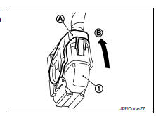
After installing the ABS actuator and electric unit (control unit) harness connector (1), move the lever (A) in the direction (B) to secure the locking.
 Sensor rotor
Front sensor rotor
FRONT SENSOR ROTOR : Removal and Installation
The front wheel sensor rotor is an integral part of the wheel
hub and bearing assembly and cannot be disassembled.
Refer to FAX- ...
 VDC off switch
Removal and Installation
REMOVAL
Remove the instrument lower panel LH. Refer to IP-21,
"Removal and Installation".
Remove the switch plate screws and remove the switch plate. ...
Other materials:
C1116 Stop lamp switch
DTC Logic
DTC DETECTION LOGIC
DTC
Display item
Malfunction detected condition
Possible cause
C1116
STOP LAMP SW
When stop lamp switch circuit is open.
Harness or connector
Stop lamp switch
ABS actuator and electric unit
(control unit)
...
Brake warning lamp
Component Function Check
1.CHECK BRAKE WARNING LAMP FUNCTION (1)
Check that brake warning lamp in combination meter turns ON for
approximately 2 seconds after ignition
switch is turned ON.
Is the inspection result normal?
YES >> GO TO 2.
NO >> Proceed to diagnosis procedure. ...
P0443 EVAP Canister purge volume control solenoid valve
DTC No.
CONSULT screen terms
(Trouble diagnosis content)
DTC detecting condition
Possible cause
P0443
PURG VOLUME CONT/V
(Evaporative emission system
purge control valve circuit)
A
The canister purge flow is detected during
the vehicle is stopped while t ...
