Nissan Sentra Service Manual: Unit disassembly and assembly
Center console assembly
Exploded View
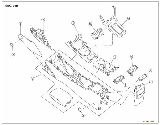
- Center console upper finisher
- Center console side finisher (RH)
- Center console side finisher (LH)
- Center console side finisher screw cover (LH/RH)
- Center console assembly
- Center console screw cover (LH/RH)
- Center console rear finisher
- Center console rear finisher cover
- Center console coin tray (if equipped)
- Heated seat switch finisher (if equipped)
- Center console cup holder finis
- Shift selector finisher
- Storage bin
Disassembly and Assembly
DISASSEMBLY
- Remove the center console assembly. Refer to IP-17, "Removal and Installation".
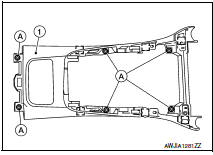
- Remove the center console upper finisher.
- Remove the center console upper finisher screws (A).
- Release the center console upper finisher pawls using a suitable tool.
 : Pawl
- Remove the center console upper finisher (1).
- Remove the center console rear finisher
- Release the center console rear finisher cover pawls using a suitable tool, then remove the center console rear finisher cover (1).
 : Pawl
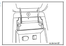
- Release the center console rear finisher clips using a suitable tool, then remove the center console rear finisher (1).
 : Metal clip
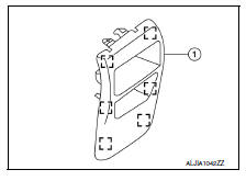
- Release the center console accessory finisher pawls using a suitable tool and remove.
ASSEMBLY
Assembly is in the reverse order of disassembly.
 Glove box assembly
Removal and Installation
REMOVAL
Remove the instrument side finisher RH using a suitable tool.
Remove the glove box assembly upper screws (A).
Remove the glove box assembly lower scre ...
 Seat
Seat
...
Other materials:
Precaution for Supplemental Restraint System (SRS) "AIR BAG"
and "SEAT BELT PRE-TENSIONER"
The Supplemental Restraint System such as “AIR BAG” and “SEAT
BELT PRE-TENSIONER”, used along
with a front seat belt, helps to reduce the risk or severity of injury to the
driver and front passenger for certain
types of collision. Information necessary to service the system ...
Storage pouch
A storage pouch is located on the front of the
driver’s and passenger’s seats.
WARNING
Do not store angular, sharp, heavy objects
or objects that cannot fully fit inside
the pouch because they might increase
the likelihood of an injury in a
crash.
To ensure ...
Diagnosis system (BCM) (without intelligent key system)
Common item
Common item : consult function (bcm - common item)
APPLICATION ITEM
CONSULT performs the following functions via CAN communication with BCM.
Direct Diagnostic Mode
Description
ECU identification
The BCM part number is displayed.
Self Diagnostic Result
...
