Nissan Sentra Service Manual: Turn signal lamp circuit
Description
The bcm monitors inputs from the combination switch to determine when to activate the turn signals. The bcm outputs voltage direction to the left and right turn signals during turn signal operation or both during hazard warning operation. The bcm sends a turn signal indicator request to the combination meter via the can communication lines.
The bcm performs the fast flasher operation (fail-safe) if any bulb or harness of the turn signal lamp circuit is open.
Note:
Turn signal lamp blinks at normal speed when using the hazard warning lamp.
Component function check
1.Check turn signal lamp
 Consult
- Select FLASHER of BCM (FLASHER) active test item.
- With operating the test items, check that the turn signal lamp blinks.
Lh : turn signal lamps (lh) on
Rh : turn signal lamps (rh) on
Off : the turn signal lamps off
Does the turn signal lamp blink? Yes >> turn signal lamp circuit is normal.
No >> refer to exl-99, "diagnosis procedure".
Diagnosis procedure
Regarding wiring diagram information, refer to exl-58, "wiring diagram".
1.Check turn signal lamp bulb
Check the applicable lamp bulb to be sure the proper bulb standard is in use and the bulb is not open.
Is the bulb ok? Yes >> go to 2.
No >> replace the bulb.
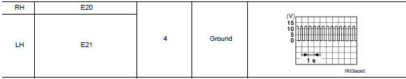
2.Check turn signal lamp output voltage
- Turn the ignition switch off.
- Disconnect the front or rear combination lamp harness connector or the door mirror harness connector (if equipped with turn signal in mirror) in question.
- Turn the ignition switch on.
- Operate the turn signal switch.
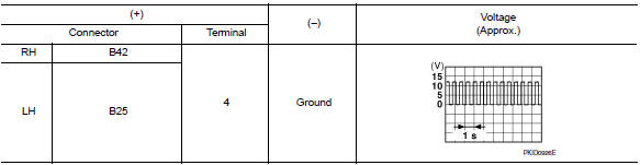
- While the turn signal is operating, check the voltage between the front combination lamp harness connector and ground.
![]()
- While the turn signal is operating, check the voltage between the rear combination lamp harness connector and ground.
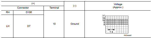
- While the turn signal is operating, check the voltage between the door mirror harness connector and ground.
Is the inspection result normal? Yes >> go to 5.
No >> go to 3.
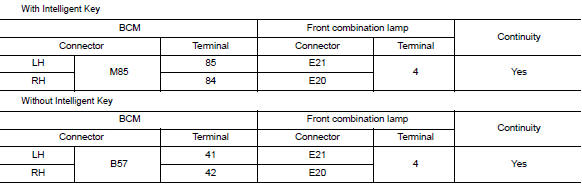
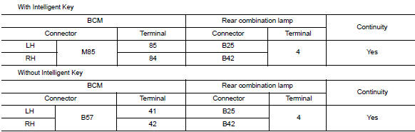
3.Check turn signal lamp circuit for open
- Turn the ignition switch off.
- Disconnect bcm harness connector in question.
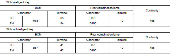
- Check continuity between the bcm harness connector and the front combination lamp harness connector.
- Check continuity between the BCM harness connector and the rear combination lamp harness connector.
- Check continuity between the BCM harness connector and the door mirror harness connector in question.
Is the inspection results normal? YES >> GO TO 4.
NO >> Repair or replace the harness or connectors.
4.Check turn signal lamp short circuit
- Check continuity between the bcm harness connector and ground.
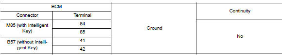
Are the inspection results normal? YES >> Replace BCM. Refer to BCS-73, "Removal and Installation" (with Intelligent Key system) or BCS- 126, "Removal and Installation" (without Intelligent Key system).
NO >> Repair or replace the harness or connectors.
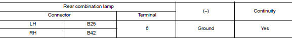
5.Check turn signal lamp ground circuit
- Turn the ignition switch OFF.
- Check continuity between the front combination lamp harness connector or the rear combination lamp harness connector or the door mirror harness connector in question and ground.


- Check continuity between the rear combination lamp harness connector and ground.
- Check continuity between the door mirror harness connector and ground.
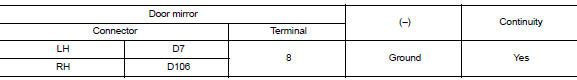
Are the inspection results normal? YES >> Replace the malfunctioning lamp.
NO >> Repair or replace the harness or connectors.
 Parking lamp circuit
Description
The ipdm e/r (intelligent power distribution module engine room) controls the
tail lamp relay based on inputs
from the bcm over the can communication lines. When the tail lamp relay i ...
 Optical sensor
Description
The optical sensor measures ambient light and transmits the optical sensor
signal to the bcm.
Component function check
1.Check optical sensor signal by consult
Consult
Turn the ...
Other materials:
Brake precautions
Vacuum assisted brakes
The brake booster aids braking by using engine
vacuum. If the engine stops, you can stop the
vehicle by depressing the brake pedal. However,
greater foot pressure on the brake pedal will be
required to stop the vehicle and stopping distance
will be longer.
Using the bra ...
B0096 Front side air bag satellite sensor RH
Description
DTC B0096 FRONT SATELLITE SENSOR RH
The front side air bag satellite sensor RH is wired to the air bag diagnosis
sensor unit. The air bag diagnosis
sensor unit will monitor the front side air bag satellite sensor RH for internal
failures and its circuits for communication
errors ...
Harness connector
Description
Harness connector (tab-locking type)
The tab-locking type connectors help prevent accidental looseness or
disconnection.
The tab-locking type connectors are disconnected by pushing or lifting
the locking tab(s). Refer to the figure
below.
Refer to the next page for desc ...
