
Nissan Sentra Service Manual: System description
Component parts
Component parts location
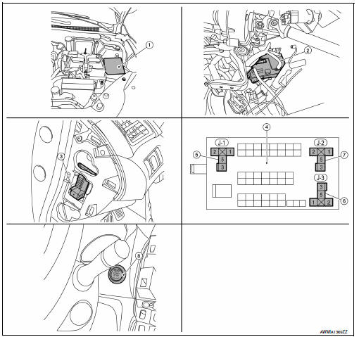
- Ipdm e/r (contains ignition relay-1)
- Bcm (view with instrument panel removed)
- Fuse block (j/b) (front)
- Fuse block (j/b) (back)
- Blower relay
- Ignition relay-2
- Accessory relay-1
- Push-button ignition switch
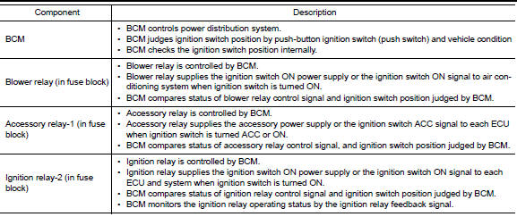
Component description

System
Power distribution system
Power distribution system : system diagram
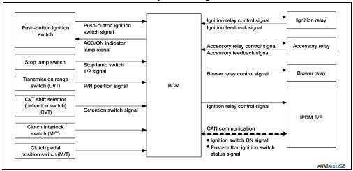
Power distribution system : system description
System description
- PDS (POWER DISTRIBUTION SYSTEM) is the system that BCM controls with the operation of the pushbutton ignition switch and performs the power distribution to each power circuit. This system is used instead of the mechanical power supply changing mechanism with the operation of the conventional key cylinder.
- The push-button ignition switch can be operated when intelligent key is in the following condition.
- Intelligent key is in the detection area of the inside key antenna.
- Intelligent key backside is contacted to push-button ignition switch.
- The push-button ignition switch operation is input to bcm as a signal. Bcm changes the power supply position according to the status and operates the following relays to supply power to each power circuit.
- Ignition relay-1
- Ignition relay-2
- Accessory relay-1
- Accessory relay-2
- Blower relay
Note:
The engine switch operation changes due to the conditions of brake pedal, selector lever and vehicle speed.
- The power supply position can be confirmed with the lighting of the indicators in the push-button ignition switch.
Battery saver system
When all the following conditions are met for 30 minutes, the battery saver system will cut off the power supply to prevent battery discharge.
- The ignition switch is in the ACC or ON position
- All doors are closed
- Selector lever is in the p (park) position
Reset condition of battery saver system
In order to prevent the battery from discharging, the battery saver system will cut off the power supply when all doors are closed, the selector lever is in p (park) position and the ignition switch is left in the acc or on position for 30 minutes. If any of the following conditions are met the battery saver system is released and the steering will change automatically to lock position from off position.
- Opening any door
- Operating door request switch on door handle
- Operating Intelligent Key
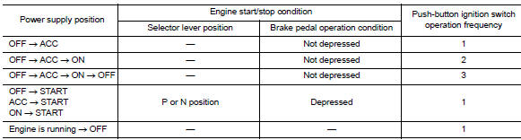
Power supply position change table by push-button ignition switch operation
The power supply position changing operation can be performed with the following operations.
Note:
- When an Intelligent Key is within the detection area of inside key antenna and when Intelligent Key backside is contacted to push-button ignition switch, it is equivalent to the operations below.
- When starting the engine, the BCM monitors under the engine start conditions:
- Brake pedal operating condition
- Selector lever position
- Vehicle speed
Vehicle speed: less than 4 km/h (2.5 MPH)
Vehicle speed: 4 km/h (2.5 Mph) or more

Emergency stop operation
- Press and hold the push-button ignition switch for 2 seconds or more.
- Press the push-button ignition switch 3 times or more within 1.5 Seconds.
 Precaution
Precaution for supplemental restraint system (srs) "air bag" and "seat belt
pre-tensioner"
The Supplemental Restraint System such as “AIR BAG” and “SEAT BELT PRE- ...
 Diagnosis system (BCM)
Common item
Common item : consult function (bcm - common item)
Application item
Consult performs the following functions via can communication with bcm.
System application
Bcm can perform the ...
Other materials:
P0196 EOT Sensor
DTC Logic
DTC DETECTION LOGIC
NOTE:
If DTC P0196 is displayed with DTC P0197 or P0198, first perform the
trouble diagnosis for DTC P0197 or
P0198. Refer to EC-264, "DTC Logic".
DTC No.
CONSULT screen terms
(Trouble diagnosis content)
DTC detecting condition
Possib ...
G Sensor
Exploded View
G sensor
Bracket
Vehicle front
NВ·m (kg-m, ft-lb)
NВ·m (kg-m, in-lb)
Removal and Installation
WARNING:
Do not leave any objects (screwdrivers, tools, etc.) on the seat during
seat repair. It can lead to personal
injury if the side air bag module should acc ...
DTC/circuit diagnosis
P1610 LOCK MODE
Description
ECM forcibly switches to the mode that inhibits engine start, when engine
start operation is performed 5 times
or more while communication between ECM and BCM is not normal.
DTC Logic
DTC DETECTION LOGIC
NOTE:
If DTC P1610 is displayed with other DTC (for BCM or ...
