Nissan Sentra Service Manual: Removal and installation
REAR WHEEL HUB
Exploded View - Drum brake
DRUM BRAKE
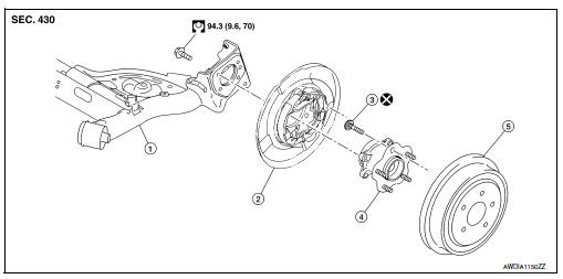
- Rear suspension beam
- Brake assembly
- Wheel stud
- Wheel hub assembly (Bearing-integrated type)
- Brake drum
Removal and Installation - Drum brake
REMOVAL
- Remove the wheel and tire using power tool. Refer to WT-47, "Removal and Installation".
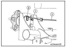
- Remove the rear wheel sensor bolt (1) and the rear wheel sensor (2). Refer to BRC-107, "REAR WHEEL SENSOR : Removal and Installation".
- Remove rear brake drum. Refer to BR-42, "Removal and Installation".
CAUTION:
Do not depress brake pedal while rear brake drum is removed.
- Remove the hub bolts and wheel hub assembly.
CAUTION:
Do not remove parking brake assembly. Protect it from falling.
INSTALLATION
Installation is in the reverse order of removal.
- Check that the wheel hub assembly operates smoothly
- Perform inspection after installation. Refer to RAX-8, "Inspection".
Exploded View - Disc brake
DISK BRAKE
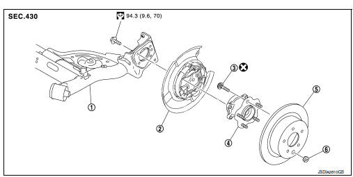
- Rear suspension beam
- Parking brake assembly
- Wheel stud
- Wheel hub assembly (Bearing-integrated type)
- Disc rotor
- Plug
Removal and Installation - Disc brake
REMOVAL
- Remove the wheel and tire using power tool. Refer to WT-47, "Removal and Installation".
- Remove the rear wheel sensor bolt (1) and the rear wheel sensor (2). Refer to BRC-107, "REAR WHEEL SENSOR : Removal and Installation".
- Remove the rear brake caliper assembly. Refer to BR-47, "BRAKE CALIPER ASSEMBLY : Removal and Installation".
CAUTION:
Do not depress brake pedal while rear brake assembly is removed.
- Remove the hub bolts and wheel hub assembly.
CAUTION:
Do not remove parking brake assembly. Protect it from falling.
INSTALLATION
Installation is in the reverse order of removal.
- Align the matching marks that have been made during removal when reusing the disc rotor.
- Check that the wheel hub assembly operates smoothly
- Perform inspection after installation. Refer to RAX-8, "Inspection".
Inspection
INSPECTION AFTER REMOVAL
Check the wheel hub assembly for wear, cracks, and damage. Replace if necessary.
INSPECTION AFTER INSTALLATION
- Check wheel sensor harness for proper connection. Refer to BRC-107, "REAR WHEEL SENSOR : Exploded View".
- Adjust parking brake operation (stroke). Refer to PB-4, "Inspection and Adjustment".
- Check wheel alignment. Refer to RSU-6, "Inspection".
 Periodic maintenance
REAR WHEEL HUB
Inspection
COMPONENT PART
Check the mounting conditions (looseness, back lash) of each component and
component conditions (wear,
damage) are normal.
WHEEL HUB ASSEMBLY (BEARING-I ...
 Service data and specifications (SDS)
Wheel Bearing
...
Other materials:
Precaution
Precaution for supplemental restraint system (srs) "air bag" and "seat belt pre-tensioner"
The Supplemental Restraint System such as “AIR BAG” and “SEAT BELT PRE-TENSIONER”,
used along
with a front seat belt, helps to reduce the risk or severity of injury ...
Tcm branch line circuit
Diagnosis procedure
1.Check connector
Turn the ignition switch off.
Disconnect the battery cable from the negative terminal.
Check the following terminals and connectors for damage, bend and loose
connection (unit side and connector
side).
Tcm
Harness connector f50
Harness co ...
Service data and specifications (SDS)
General Specifications
Clutch Pedal
Clutch Disc
Clutch Cover
...
