Nissan Sentra Service Manual: Can communication circuit
Diagnosis procedure
1.Connector inspection
- Turn the ignition switch off.
- Disconnect the battery cable from the negative terminal.
- Disconnect all the unit connectors on CAN communication system.
- Check terminals and connectors for damage, bend and loose connection.
Is the inspection result normal? YES >> GO TO 2.
NO >> Repair the terminal and connector.
2.Check harness continuity (short circuit)
Check the continuity between the data link connector terminals.
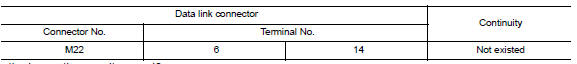
Is the inspection result normal? Yes >> go to 3.
No >> check the harness and repair the root cause.
3.Check harness continuity (short circuit)
Check the continuity between the data link connector and the ground.
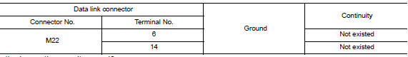
Is the inspection result normal? Yes >> go to 4.
No >> check the harness and repair the root cause.
4.Check ecm and bcm termination circuit
- Remove the ecm and the bcm.
- Check the resistance between the ECM terminals.
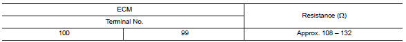
- Check the resistance between the bcm terminals.
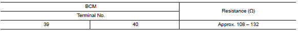
Is the measurement value within the specification? YES >> GO TO 5.
NO >> Replace the ECM and/or the BCM.
5.Check symptom
Connect all the connectors. Check if the symptoms described in the “symptom (results from interview with customer)” are reproduced.
Inspection result
Reproduced>>GO TO 6.
Non-reproduced>>Start the diagnosis again. Follow the trouble diagnosis procedure when past error is detected.
6.Check unit reproduction
Perform the reproduction test as per the following procedure for each unit.
- Turn the ignition switch off.
- Disconnect the battery cable from the negative terminal.
- Disconnect one of the unit connectors of can communication system.
Note:
Ecm and bcm have a termination circuit. Check other units first.
- Connect the battery cable to the negative terminal. Check if the symptoms described in the “symptom (results from interview with customer)” are reproduced.
Note:
Although unit-related error symptoms occur, do not confuse them with other symptoms.
Inspection result
Reproduced>>connect the connector. Check other units as per the above procedure.
Non-reproduced>>replace the unit whose connector was disconnected.
 Bcm branch line circuit
Diagnosis Procedure
1.Check connector
Turn the ignition switch off.
Disconnect the battery cable from the negative terminal.
Check the terminals and connectors of the BCM for damage, bend and ...
 Can system (type 4)
Dtc/circuit diagnosis ...
Other materials:
Ecu diagnosis information
Av control unit
Reference value
TERMINAL LAYOUT
PHYSICAL VALUES
Dtc index
...
System description
Component parts
Component parts location
Ipdm e/r (contains ignition relay-1)
Bcm (view with instrument panel removed)
Fuse block (j/b) (front)
Fuse block (j/b) (back)
Blower relay
Ignition relay-2
Accessory relay-1
Push-button ignition switch
Component description
...
Harness connector
Description
Harness connector (tab-locking type)
The tab-locking type connectors help prevent accidental looseness or
disconnection.
The tab-locking type connectors are disconnected by pushing or lifting
the locking tab(s). Refer to the figure
below.
Refer to the next page for desc ...
