Nissan Sentra Service Manual: Brake booster
Inspection
Operation
Depress the brake pedal several times at five second intervals with the engine stopped. Start the engine with the brake pedal fully depressed. Check that the clearance between brake pedal and dash lower panel decreases.
NOTE:
A slight impact with a small click may be felt on the pedal when the brake pedal is fully depressed. This is normal brake system operation.
Vacuum Inspection
Idle the engine for one minute to apply vacuum to the brake booster.
Stop the engine. Depress the brake pedal several times at five second intervals until the accumulated vacuum is released to atmospheric pressure. Check that the clearance between brake pedal and dash lower panel gradually increases (A → B → C) each time the brake pedal is depressed during this operation.
Depress the brake pedal with the engine running. Then stop the engine while holding down the brake pedal. Check that the brake pedal stroke does not change after holding down the brake pedal for 30 seconds or more.
NOTE:
A slight impact with a small click may be felt on the pedal when the brake pedal is fully depressed. This is normal brake system operation.
 Brake master cylinder
Inspection
Check for brake fluid leakage at the following areas:
Master cylinder mounting face
Reservoir tank mounting face
Brake tube and brake tube connections
Brake hose and brake hose ...
 Front disc brake
BRAKE PAD
BRAKE PAD : Inspection
PAD WEAR
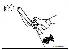
Check brake pad thickness from an inspection hole on caliper body.
Check using a scale if necessary
Wear limit thickness : Refer to BR-55, "Front ...
Other materials:
Precaution
Precaution for supplemental restraint system (srs) "air bag" and "seat belt
pre-tensioner"
The Supplemental Restraint System such as “AIR BAG” and “SEAT BELT PRE-TENSIONER”,
used along
with a front seat belt, helps to reduce the risk or severity of injur ...
Heater operation
This mode is used to direct heated air to the foot
outlets. Some air also flows from the defrost
outlets and the side vent outlets.
Press the button to the OFF
position
for normal heating.
Press the air flow control
button.
Turn the fan control dial to the desired position.
Tur ...
NISSAN vehicle immobilizer system
The NISSAN Vehicle Immobilizer system will not
allow the engine to start without the use of the
registered key.
If the engine fails to start using a registered key
(for example, when interference is caused by
another registered key, an automated toll road
device or automatic payment device o ...
